

Table of Contents
Introduction
In a commercial gym, bench design is simple: add steel, add weld, and nobody complains about weight or floor space. A home gym flips that. The bench has to feel as solid as a commercial one under a heavy press, then be easy to move and compact enough to tuck into a corner.
That conflict between rigidity and portability decided almost every choice in this design. Here is how I worked through it, from body dimensions to the final CAD in SolidWorks.
These competing requirements are central to FID bench design in SolidWorks, where structural rigidity, portability and manufacturing cost must be considered together.
The brief
An adjustable bench with flat, incline and decline positions, built for garage lifters and people short on space. The targets:
- Rated working load of 300 kg (lifter plus barbell or dumbbells)
- Compact footprint on a wide, stable base
- Easy to move with a front carry handle
- Ships flat-pack and stays cheap to manufacture
Engineering Challenges and Design Trade-offs
Designing a compact, heavy-duty FID (Flat, Incline, Decline) bench requires balancing structural strength, portability, user comfort and manufacturing cost. These requirements often compete with one another, making the design process an exercise in engineering trade-offs rather than simply selecting stronger materials.
The primary challenges in this SolidWorks bench design were:
- Structural strength versus overall weight: The bench was designed around a target working load of 300 kg, including the user and weights. Increasing the thickness of every steel member would add unnecessary weight and material cost. Instead, the design uses 60 × 60 × 3 mm square tubing and a localized 4 mm gusset beneath the main pivot to reinforce a critical region.
- Stability versus compact footprint: A home gym bench needs sufficient support at the front and rear to resist movement during exercise, but an oversized base can make storage difficult. The design uses wide stabilizers with ribbed rubber feet to balance floor contact, stability and practical handling.
- Adjustment flexibility versus locking reliability: Flat, incline and decline exercises require multiple backrest positions, along with seat-angle adjustment. The challenge was to provide convenient adjustments without introducing excessive play or relying on a locking mechanism that could disengage unintentionally. A spring-loaded 16 mm steel cross-pin and a 4 mm sawtooth adjustment ladder form the backrest locking arrangement.
- Manufacturing efficiency versus component complexity: A design with too many unique parts can increase purchasing, fabrication and assembly costs. Standardizing the square-tube sections and using laser-cut features helps simplify material procurement and component positioning during welding.
These decisions demonstrate an important principle in mechanical product design: performance depends on how the entire structure works together. Frame geometry, load paths, pivot locations, adjustment hardware and manufacturing methods must be considered as one integrated system.
Start with the human, not the frame
Before sketching a single tube, I fixed the dimensions that touch the lifter’s body.
| Parameter | Value | Why |
|---|---|---|
| Bench height | 430 mm | Within the 420-450 mm IPF range; keeps feet flat for shorter users |
| Pad width | 280 mm at lower back, 260 mm at shoulders | Frees the shoulder blades during presses |
| Seat-to-back gap | ≤ 35 mm | Keeps the lower back supported in flat position |
Height. At 430 mm, including board and foam, most shorter users can still plant their feet and drive through the floor. Much taller and that stability starts to go.
Width. I know this is narrower than competition benches (IPF asks for 290 mm or more). That was deliberate. Home users do far more dumbbell work, and a tapered upper pad leaves the shoulder blades room to retract. If you plan competition-style barbell benching, go wider.
Gap. Big gaps between the back and seat pads leave the lower back unsupported when you’re flat. I held it to 35 mm.
The frame: strength from geometry, not just thickness
The main spine is a 60 × 60 × 3 mm square tube (Q235B / ASTM A500 Gr.B class). One tube size also runs through the spine and base cross-members, so purchasing stays simple.
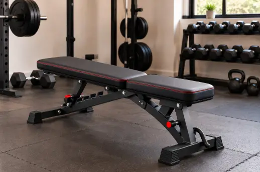
Thicker wall was the lazy answer. Instead I welded a 4 mm laser-cut gusset under the main pivot node, where the bending moment peaks. It raises the effective section depth exactly where the frame needs it.
For validation, I designed against the load cases in EN ISO 20957-1, and the bench should be tested physically, not just simulated.
Base and handling: stable under load, easy to move
The base is a wide front and rear stabilizer, each ending in ribbed rubber feet, so the bench stays planted under a heavy press. The front support is an arched steel column that carries the seat, and a curved grab handle on the front stabilizer makes it easy to lift and reposition the bench.
Adjustment: positive lock, no rattle
I wanted one-handed angle changes with zero play. The solution is a 4 mm laser-cut sawtooth ladder welded to the spine, with a 16 mm solid steel cross-pin on the backrest frame.
The cross-pin is spring-loaded with a red pull knob, so one hand lifts it, slides the backrest and drops it into the next slot. A second red-knob pin on the front column sets the seat angle.
The notches have a 12° negative (undercut) angle. Press down on the backrest and the pin gets pulled deeper into the notch root instead of walking out, which is the behavior you want mid-set. Bearing check on the pin and ladder.
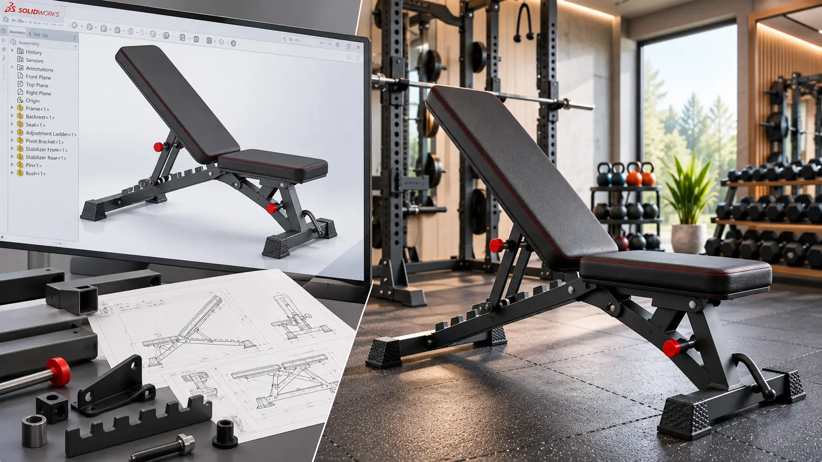
In FID bench design in SolidWorks, modelling these adjustment components within the assembly helps engineers examine their interfaces and clearances across different backrest and seat positions.
SolidWorks Design and Validation Workflow
SolidWorks provides a practical environment for developing adjustable mechanical products because the frame, moving components and interfaces can be evaluated together before manufacturing begins.
For a fitness bench of this type, a structured CAD workflow can include the following stages.
- Parametric part modelling: Create the primary frame members, support columns, adjustment ladder, pivot brackets, seat frame and backrest frame as individual parts. Key dimensions such as tube size, pivot locations and support spacing should be controlled through editable parameters wherever practical.
- Assembly modelling and motion checks: Assemble the components and define the pivot relationships between the frame, seat and backrest. Check the different adjustment positions for interference, pin engagement and potential collisions between moving components.
- Manufacturing drawing preparation: Generate fabrication drawings with dimensions, hole locations, weld details, material specifications and relevant tolerances. Laser-cut profiles and tube interfaces should be defined clearly enough to support repeatable fabrication.
- Design-for-manufacturing review: Review the assembly for standardized components, practical weld access, simplified fixturing and efficient packaging. Features such as tab-and-slot locations can help position brackets consistently during fabrication.
- Structural evaluation and physical testing: Identify the relevant load cases and critical regions, particularly the main pivot, support members, adjustment ladder and locking pins. Where appropriate, finite element analysis (FEA) can help assess stress distribution and deformation under defined loading conditions.
The design should also be evaluated against applicable safety requirements and subjected to appropriate physical testing. CAD modelling and simulation alone do not establish that a finished fitness product is safe or compliant.
This workflow helps connect the digital model with the engineering decisions required for a manufacturable product.
Presets:
- Backrest: -15° decline, 0° flat, 15° / 30° / 45° / 60° / 75° incline, 90° upright
- Seat: 0° / 15° / 25° (a raised seat front stops the lifter sliding down on steep inclines)
Hardware and upholstery
Pivots. Flanged self-lubricating bronze bushings are pressed into every rotating joint. A bolt running directly through a raw steel tube will ovalize the hole over time. The bushing removes the wear and the side-to-side play. Fasteners are class 8.8 with nyloc nuts, because vibration loosens everything eventually.
Pads. 15 mm exterior-grade plywood base, a firm foam layer so heavy dumbbell loads don’t bottom out, and a thin softer top layer for comfort. Cover is textured, anti-slip, sweat-resistant PVC with double-stitched seams in red contrast thread.
Designed to be built cheaply
- One tube size keeps raw material stock simple
- Tab-and-slot laser notches locate brackets and gussets before welding, which cuts down on welding fixtures
- Flat-pack shipping: spine, backrest frame, seat frame, feet and pads ship in one carton (about 1180 × 380 × 180 mm)
Manufacturing and Safety Considerations
A mechanically sound CAD model must also translate into a product that can be fabricated, assembled, inspected and maintained consistently.
For an adjustable FID bench, several details deserve particular attention before production.
- Weld quality and joint geometry: The main pivot and load-bearing frame connections require appropriate weld specifications, joint preparation and inspection criteria.
- Locking mechanism reliability: The adjustment pins and sawtooth ladder should be checked for bearing stress, local deformation, wear and reliable engagement across the intended positions.
- Base stability: The stabilizer geometry and rubber feet should be evaluated for tipping, sliding and uneven floor contact under relevant loading conditions.
- Material and fastener specifications: Steel grades, wall thicknesses, fastener grades and bushing specifications should be documented consistently in the engineering drawings and bill of materials.
- Physical testing: The proposed 300 kg working load is a design target, not proof of a verified load rating. Appropriate testing should establish the product’s performance under defined loading conditions, including relevant static, dynamic and durability assessments.
The design references EN ISO 20957-1 for validation planning. The applicable edition, relevant product-specific requirements and test procedures should be confirmed before making any compliance claim.
A complete manufacturing package should give the production team enough information to build the product consistently while supporting the required quality and safety checks.
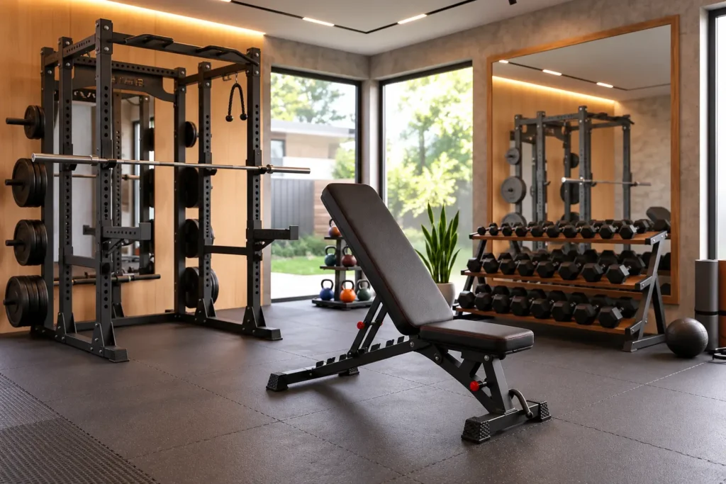
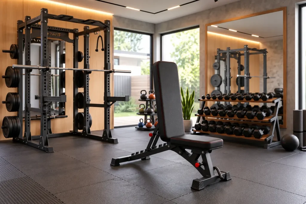
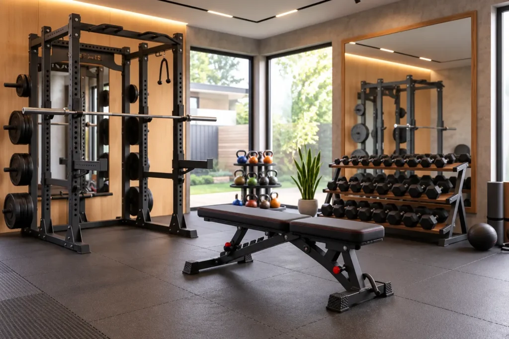
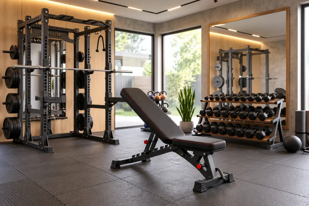
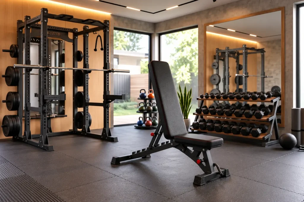
The bench in a home gym setup
To check how the bench sits next to a rack and dumbbell storage, here it is in a typical home gym layout. These are illustrative renders, not photographs of a production unit.
Immersiv Techsphere’s Approach to Mechanical Product Design
At Immersiv Techsphere, mechanical product design involves more than creating a 3D model. The objective is to develop engineering designs that consider product function, structural requirements, manufacturing methods and practical assembly.
For products such as adjustable fitness equipment, our mechanical design support can include:
- 3D CAD modelling and assembly design: Developing parametric parts and assemblies in SolidWorks to define the product structure and component interfaces.
- Design for Manufacturing (DFM): Reviewing material selection, sheet metal or tube fabrication, weld access, component standardization and assembly requirements.
- Manufacturing drawings: Preparing dimensioned engineering drawings, fabrication details, and relevant production documentation.
- CAD automation: Automating repetitive modelling and drawing tasks to improve consistency and reduce manual engineering effort.
- Engineering visualization: Creating 3D renders and technical animations to communicate product features, assembly sequences and design concepts.
For fitness equipment manufacturers and product development teams, this type of engineering support can help organize the transition from an initial concept to a detailed CAD design and manufacturing documentation.
The scope of support depends on the product, available design inputs and validation requirements. Structural performance and product safety should be verified through appropriate engineering analysis and physical testing where required.
Need mechanical design support for a new product? Visit Immersiv Techsphere to explore our mechanical design, CAD automation and industrial visualization services.
FAQs
Engineers should consider the intended working load, frame geometry, material selection, base stability, adjustment mechanism, user ergonomics and manufacturing cost. These factors must work together to achieve a balance between structural strength, usability and manufacturability.
SolidWorks is used to create 3D parts and assemblies, evaluate component interfaces, check clearances across adjustment positions and generate manufacturing drawings. Simulation tools can also support structural evaluation when required.
Designers can optimize frame geometry, standardize tube sections and add reinforcement selectively at critical load-bearing areas. Any weight reduction should be assessed through engineering calculations, appropriate simulation and physical testing.
A reliable locking mechanism requires adequate pin engagement, suitable bearing surfaces, controlled clearances and resistance to unintended disengagement. Engineers should also consider wear and durability during repeated adjustment cycles.
DFM can reduce manufacturing complexity through standardized components, laser-cut profiles, tab-and-slot features and simplified assembly. These approaches can help minimize material variety, reduce fixture requirements and improve fabrication consistency.
FID Bench Design in SolidWorks: Key Engineering Considerations
The design decisions discussed above illustrate how frame geometry, pivot reinforcement, adjustment mechanisms and manufacturing requirements influence the development of an adjustable FID bench in SolidWorks.
What I’d tell another designer
Home gym equipment isn’t a lighter commercial bench. It’s a different optimization problem. Every gram you remove and every second you save adjusting has to be paid for in rigidity, and the paying happens in the details: where the gusset goes, which part carries the load, which joint gets a bushing.
Conclusion: Balancing Strength, Functionality and Manufacturability
Designing a compact, heavy-duty FID bench is a mechanical engineering challenge that extends beyond creating a strong steel frame. Structural rigidity, user ergonomics, adjustment flexibility, portability and manufacturing cost must all be considered during product development.
In this design, the square-tube frame, localized pivot reinforcement, sawtooth adjustment ladder, spring-loaded locking pins and standardized fabrication components illustrate how individual engineering decisions contribute to the overall product concept.
SolidWorks provides a structured environment for developing the 3D model, coordinating component interfaces and preparing manufacturing documentation. However, the CAD model must be supported by appropriate engineering evaluation and physical testing before the proposed load capacity and safety performance can be confirmed.
For manufacturers, integrating mechanical design, Design for Manufacturing (DFM) and validation planning early in the development process can help identify potential issues before they affect production.
Immersiv Techsphere supports businesses with mechanical CAD design, manufacturing drawings, CAD automation and industrial animation services, helping engineering teams manage product development and technical documentation requirements.
Have a Project in Mind?
Need help with 3D animation, industrial visualization, HSE training animation, or product visualization? Tell us about your project and our team will get back to you.