


Table of Contents
Introduction
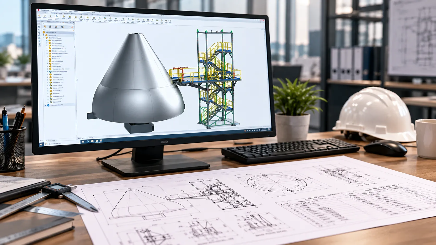
Fixture design for manufacturing is more than creating a 3D model that holds a component in place. A production fixture must locate the workpiece accurately, constrain it securely, provide accessibility for machining or assembly, and remain practical for operators and manufacturing teams.
The process typically starts with a 3D CAD model and ends with a complete set of production-ready drawings, BOMs, component details, and manufacturing documentation.
A well-developed fixture design connects several engineering decisions:
Part requirements → locating strategy → clamping → fixture structure → 3D CAD model → engineering validation → detailed drawings → BOM → manufacturing
For manufacturers producing repeated components or assemblies, this workflow can improve repeatability, simplify production operations, and reduce ambiguity between design and manufacturing teams.
Immersiv Techsphere provides machines and fixtures design along with mechanical design, drafting, and engineering documentation to support manufacturing-focused workflows.
What Is Fixture Design for Manufacturing?
A manufacturing fixture is a device used to locate, support, and restrain a workpiece during operations such as machining, welding, inspection, fabrication, or assembly.
Unlike a general-purpose support, a fixture is designed around the geometry and process requirements of a specific component or operation.
Depending on the application, fixture design may include:
- Machining fixtures
- Welding fixtures
- Assembly fixtures
- Inspection fixtures
- Drill fixtures
- Milling fixtures
- Fabrication fixtures
- Sheet metal fixtures
- Positioning fixtures
- Checking fixtures
- Modular fixtures
The design objective is not simply to hold the component. The fixture should establish a repeatable relationship between the workpiece, tooling, machine, and operator.
Why the 3D CAD Model Is the Starting Point
A fixture cannot be designed independently of the component and manufacturing process.
The first step is usually to understand the part that the fixture will locate or support. The 3D CAD model provides important information about:
- Overall geometry
- Critical surfaces
- Holes and mounting features
- Datums
- Component orientation
- Machining access
- Assembly interfaces
- Potential interference areas
- Tolerance requirements
The fixture designer can then develop the fixture around the actual component geometry.
For example, a machining fixture may use specific machined surfaces as primary locating references, while a welding fixture may need to account for joint accessibility, clamping sequence, weld distortion, and operator access.
This is why 3D CAD fixture design is closely connected to manufacturing requirements rather than being only a modelling exercise.
The Fixture Design Process: From Concept to Production
A structured fixture design workflow helps ensure that the final drawings represent a manufacturable and usable fixture.
1. Understand the Component and Manufacturing Operation
Before modelling the fixture, define the manufacturing operation.
Ask:
- What operation will be performed?
- What surfaces are already finished?
- Which surfaces are critical?
- How is the component loaded?
- How is it unloaded?
- Where will cutting tools or welding equipment access the part?
- What forces will act on the component?
- How frequently will the fixture be used?
- Does the fixture need adjustment or replaceable elements?
The answers influence almost every subsequent design decision.
A fixture intended for occasional prototype work may have a very different architecture from one intended for high-volume production.
2. Establish the Locating Strategy
Locating is one of the most important aspects of fixture design.
The fixture should establish a predictable position for the workpiece without unnecessarily restricting the component or making loading difficult.
Common locating elements include:
- Locating pins
- Rest pads
- Locating blocks
- V-blocks
- Stops
- Bushings
- Adjustable supports
- Nesting surfaces
The designer must consider the relationship between the workpiece datums and the fixture locating points.
A useful principle is to define the locating scheme around the functional requirements of the manufacturing operation, rather than simply selecting convenient surfaces.
Poor locating strategy can result in:
- Part positioning errors
- Accumulated tolerances
- Difficult loading
- Over-constrained components
- Inconsistent machining results
- Difficult inspection
3. Design the Clamping System
Locating establishes the position; clamping helps maintain that position during the operation.
Clamping force should be sufficient to resist the expected operating forces without unnecessarily deforming the workpiece.
Depending on the application, fixtures may use:
- Toggle clamps
- Screw clamps
- Pneumatic clamps
- Hydraulic clamps
- Manual clamps
- Cam clamps
- Strap clamps
- Custom clamping mechanisms
The fixture designer also needs to consider clamp accessibility.
A technically correct clamp that blocks tool access, obstructs loading, or requires excessive operator effort may not be suitable for production.
Therefore, clamping should be evaluated together with:
Workpiece accessibility + tool clearance + operator access + loading sequence + safety.
4. Develop the Fixture Concept in 3D CAD
Once the locating and clamping strategy is established, the fixture can be developed as a 3D CAD assembly.
The assembly may include:
- Base plate
- Structural supports
- Locators
- Clamps
- Pins
- Bushings
- Fasteners
- Brackets
- Replaceable wear components
- Guide elements
- Workpiece representation
A 3D assembly makes it easier to identify interference and verify whether the proposed fixture can actually be assembled and operated.
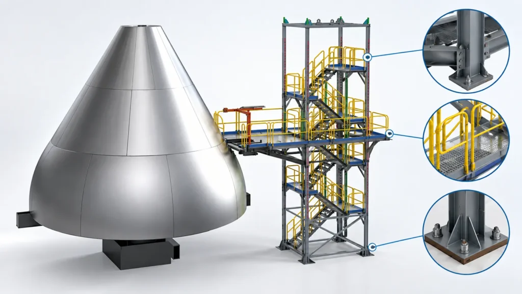
This stage is also useful for checking:
- Component clearances
- Tool access
- Fastener access
- Clamp movement
- Workpiece loading
- Maintenance access
- Replaceable components
- Overall fixture envelope
For complex mechanical assemblies, detailed 3D modelling can help connect the design concept with downstream manufacturing documentation.
5. Apply Design for Manufacturing Principles
A fixture may work conceptually but still be difficult or expensive to manufacture.
This is where Design for Manufacturing (DFM) becomes important.
The fixture design should consider the processes that will manufacture its components.
For example:
- Can the base plate be machined efficiently?
- Are the required holes accessible?
- Can standard components replace custom parts?
- Are unnecessarily tight tolerances being specified?
- Can components be assembled without special tooling?
- Can worn components be replaced?
- Are weldments accessible for fabrication?
- Are standard fasteners being used where practical?
The objective is to create a fixture that is not only functional but also manufacturable, maintainable, and practical for production.
For broader manufacturing design workflows, Immersiv Techsphere also works across mechanical design, drafting, fabrication documentation, and manufacturing-focused engineering processes.
6. Check Interference, Accessibility and Assembly
Before creating detailed drawings, the complete fixture assembly should be reviewed.
A 3D CAD review can identify issues such as:
- Clamps colliding with supports
- Fasteners that cannot be installed
- Insufficient tool clearance
- Difficult workpiece loading
- Inaccessible locator components
- Unnecessary structural material
- Interference between moving components
- Components that cannot be removed for maintenance
This review is particularly important for fixtures containing several moving or replaceable components.
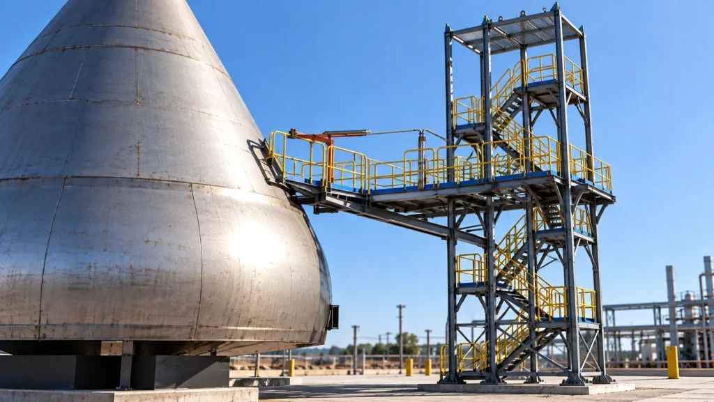
The goal is to ensure that the digital fixture behaves like a practical physical fixture.
7. Validate the Fixture Design Where Required
Not every fixture requires the same level of engineering validation.
Depending on the application, validation may include:
- Static structural analysis
- Deflection checks
- Contact considerations
- Clamping-force evaluation
- Bolt and fastener checks
- Weldment evaluation
- Fatigue considerations for repeated loading
- Motion or clearance studies
For fixtures exposed to significant loads, vibration, or repeated cycles, FEA can provide additional insight into stress and deformation before fabrication.
Immersiv Techsphere also provides FEA services for mechanical products, process equipment, and industrial assemblies.
From 3D CAD Model to Production-Ready Drawings
Creating the 3D model is only one part of fixture design.
Manufacturing requires sufficient engineering documentation to understand what to make, how to make it, and how the components fit together.
A production-ready fixture drawing package may contain several types of drawings.
1. Assembly Drawing
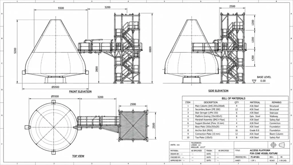
The assembly drawing communicates how the fixture components come together.
It may include:
- Assembly views
- Section views
- Item balloons
- BOM
- Overall dimensions
- Assembly notes
- Reference dimensions
- Critical interfaces
An assembly drawing should allow the manufacturing or assembly team to understand the complete fixture structure.
2. Detailed Part Drawings
Individual components that need to be manufactured require detailed drawings.
These can include:
- Base plates
- Mounting brackets
- Locator blocks
- Clamping components
- Support structures
- Custom pins
- Plates
- Weldments
- Machined components
Each drawing should communicate the information required for its manufacturing process.
3. Dimensions and Tolerances
Dimensions should communicate functional requirements without unnecessarily complicating manufacturing.
For critical fixture features, tolerances can be especially important.
Examples include:
- Hole locations
- Pin locations
- Datum surfaces
- Mounting interfaces
- Parallelism
- Perpendicularity
- Position
- Flatness
- Concentricity or runout where applicable
For projects using ASME-based drafting practices, ASME Y14.5 establishes the symbols, rules, definitions, requirements, defaults, and recommended practices used for geometric dimensioning and tolerancing.
For fixtures and gages specifically, ASME also publishes Y14.43, which addresses dimensioning and tolerancing principles for gages and fixtures.
For ISO-based workflows, ISO 1101:2017 defines the symbol language and rules for geometrical specification, including tolerances of form, orientation, location, and run-out.
The applicable drafting and tolerancing standard should always be selected according to the project’s contractual, industry, and customer requirements.
4. Material and Manufacturing Specifications
A production drawing should provide the information required to manufacture the component correctly.
Depending on the component, this may include:
- Material grade
- Thickness
- Heat treatment
- Surface finish
- Coating
- Plating
- Welding requirements
- Machining requirements
- Deburring requirements
- Surface treatment
- Special inspection requirements
For example, a fixture base plate may require a specific material and surface treatment, while a locating pin may require tighter dimensional control and a hardened surface.
5. Bill of Materials
The fixture assembly should have a structured Bill of Materials (BOM) identifying each component.
A typical BOM may include:
| Item | Description | Quantity | Material/Specification |
|---|---|---|---|
| 1 | Base Plate | 1 | As specified |
| 2 | Locating Pin | 2 | Standard/Custom |
| 3 | Support Block | 2 | Steel |
| 4 | Toggle Clamp | 2 | Standard |
| 5 | Fastener Set | As required | Standard |
The exact structure depends on the company’s documentation standards.
A well-organized BOM also helps connect engineering with purchasing, fabrication, assembly, and inventory processes.
What Makes a Fixture Drawing Production-Ready?
A production-ready drawing should answer the questions a manufacturer is likely to ask before starting work.
It should make clear:
- What is the component? Part number, revision, description, and drawing identification.
- What are its dimensions? Functional dimensions and manufacturing dimensions.
- How accurate does it need to be? Dimensional tolerances and GD&T where required.
- What material should be used? Material specification and relevant treatment requirements.
- How should it be manufactured? Machining, fabrication, welding, finishing, or other process-specific notes.
- How does it fit into the fixture? Assembly relationships and interfaces.
- What standard components are required? BOM and standard-part identification.
- How should it be inspected? Critical dimensions, datums, tolerances, and inspection requirements.
This is the difference between a 3D CAD model and a manufacturing-ready engineering package.
Common Fixture Design Mistakes to Avoid
Even technically detailed fixture models can create manufacturing problems when practical considerations are missed.
- Designing Around Geometry Instead of the Manufacturing Process: A fixture should be designed around how the component will actually be machined, welded, assembled, inspected, or handled.
- Over-Constraining the Workpiece: Too many locating points can create loading difficulties and tolerance-related problems.
- Ignoring Tool Accessibility: The component may fit perfectly inside the fixture while the cutting tool or welding equipment cannot reach the required area.
- Using Excessively Tight Tolerances: Not every feature needs the same tolerance. Over-tolerancing can increase manufacturing cost without improving fixture performance.
- Forgetting Maintenance: Wear components, locating pins, clamps, and other frequently used elements may need replacement. The fixture should allow practical maintenance.
- Creating Drawings Too Late: Waiting until the end of the design process to think about manufacturing drawings can expose missing dimensions, unclear interfaces, or incomplete component definitions.
- Not Using Standard Components: Where appropriate, standard clamps, fasteners, pins, bushings, and other components can simplify manufacturing, procurement, and maintenance.
How CAD Automation Can Improve Fixture Documentation
Fixture projects can contain many repetitive documentation tasks, particularly when similar fixtures are produced for different components or product variants.
CAD automation can support tasks such as:
- Automated drawing generation
- BOM extraction
- Custom property updates
- Drawing template application
- File naming
- PDF export
- STEP export
- DXF generation where applicable
- Revision documentation
- Standardized drawing creation
For example, a manufacturer producing several fixture variants may use parameter-driven CAD models combined with automated drawing and documentation workflows.
Immersiv Techsphere develops SolidWorks API and CAD automation solutions that can automate repetitive modelling, drawing, BOM, export, and documentation processes.
A previous Immersiv Techsphere case study demonstrates how a customized SolidWorks API workflow reduced drawing-generation time by approximately 85% for a configurable manufacturing workflow.
The principle is particularly relevant when fixture families share common design logic.
A Practical Fixture Design Workflow
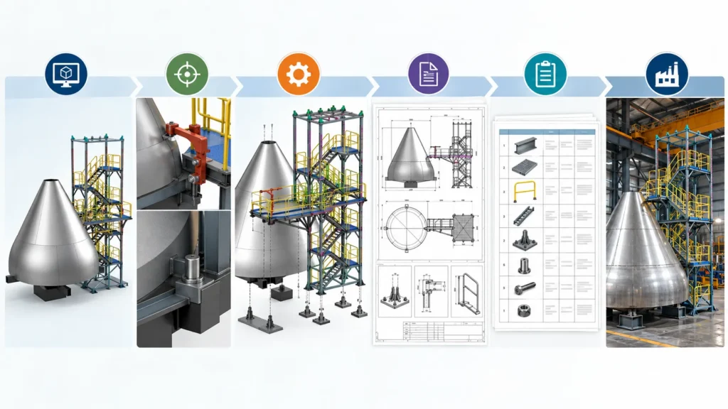
A manufacturing-oriented fixture project can follow this sequence:
- Input: 3D CAD model + 2D drawings + manufacturing requirements
- Process Review: Machining / welding / assembly / inspection requirements
- Datum & Locating Strategy: Define primary, secondary, and tertiary locating references
- Clamping Strategy: Select appropriate clamping method and force direction
- 3D Fixture Design: Develop complete CAD assembly
- Design Review: Check interference, accessibility, loading and maintenance
- Engineering Validation: Perform structural or other analysis where required
- Production Drawings: Generate assembly and component drawings
- BOM & Documentation: Prepare component list, specifications and manufacturing notes
- Manufacturing Release: Issue controlled production-ready documentation
This approach creates a clear connection between design intent and manufacturing execution.
Why Production-Ready Fixture Documentation Matters
A fixture exists to make a manufacturing operation more controlled and repeatable. If the engineering documentation is incomplete, that objective can be undermined during fabrication.
Clear drawings help reduce interpretation between:
- Design engineers
- Manufacturing engineers
- Machinists
- Fabricators
- Production teams
- Quality inspectors
- Procurement teams
The result is a more structured transition from digital design to physical manufacturing.
For engineering teams handling large numbers of drawings or repetitive documentation, combining standardized drafting practices with CAD automation can further improve consistency. Immersiv Techsphere’s CAD automation services cover workflows involving SolidWorks API, VBA, automated drawing generation, BOM generation, and engineering documentation.
FAQs About Fixture Design for Manufacturing
Fixture design is the engineering process of developing a device that locates, supports, and restrains a workpiece during manufacturing, assembly, welding, machining, or inspection.
Typical inputs include the 3D CAD model, 2D drawings, critical dimensions, datums, tolerances, manufacturing process, machine constraints, tooling requirements, loading method, and production requirements.
3D CAD allows designers to develop the fixture around the actual workpiece geometry and evaluate clearances, interference, tool accessibility, clamping, assembly, and maintenance before fabrication.
Depending on the fixture, the documentation may include an assembly drawing, detailed component drawings, BOM, manufacturing notes, tolerances, material specifications, welding details, and inspection requirements.
GD&T provides a standardized method for communicating geometric requirements. It is particularly useful for controlling critical locating features, mounting interfaces, and relationships between fixture components and workpiece datums.
Yes. Repetitive fixture families can potentially use parametric CAD, templates, macros, APIs, and automated drawing or BOM generation. The appropriate level of automation depends on how standardized the fixture design rules are.
Fixture design can be developed using platforms such as SolidWorks, Autodesk Inventor, Siemens NX, Solid Edge, and other mechanical CAD systems. The appropriate platform depends on the client’s existing engineering environment and deliverable requirements.
Conclusion
Fixture design for manufacturing is a complete engineering workflow that extends far beyond creating a 3D model.
A successful fixture connects:
Part geometry → manufacturing process → locating → clamping → 3D CAD → design validation → detailed drawings → BOM → production
The 3D CAD model establishes the digital definition of the fixture, while production-ready drawings and documentation translate that design into manufacturing requirements.
When standardized drafting, DFM principles, GD&T, engineering validation, and CAD automation are integrated into the workflow, fixture development becomes more structured and scalable.
For manufacturers developing custom fixtures, machinery, and production equipment, Immersiv Techsphere supports the workflow from mechanical design and 3D CAD modelling through engineering drawings, documentation, and CAD automation.
Have a Project in Mind?
Need help with 3D animation, industrial visualization, HSE training animation, or product visualization? Tell us about your project and our team will get back to you.