

Table of Contents
Introduction
A product idea may begin as a sketch, reference image, rough concept, or functional requirement. Turning that idea into a product that can actually be manufactured requires much more than creating a visually accurate 3D model.
Product design in SolidWorks connects conceptual design, mechanical engineering, assembly development, design validation, manufacturing considerations, and production documentation in a structured CAD workflow.
A well-built SolidWorks model does not simply represent what a product looks like. It captures design intent, dimensions, relationships, materials, configurations, assembly requirements, and manufacturing information that can support the transition from engineering to production.
SolidWorks is designed around parts, assemblies, drawings, parametric modeling, and production documentation, making it suitable for workflows that need to move from 3D product concepts toward manufacturing.
For engineering teams, the objective is therefore not just to create a 3D model. The objective is to create a manufacturing-ready CAD definition of the product.
What Does Product Design in SolidWorks Involve?
Product design in SolidWorks is the process of developing a product digitally from its initial concept through detailed engineering and manufacturing documentation.
A typical workflow can include:
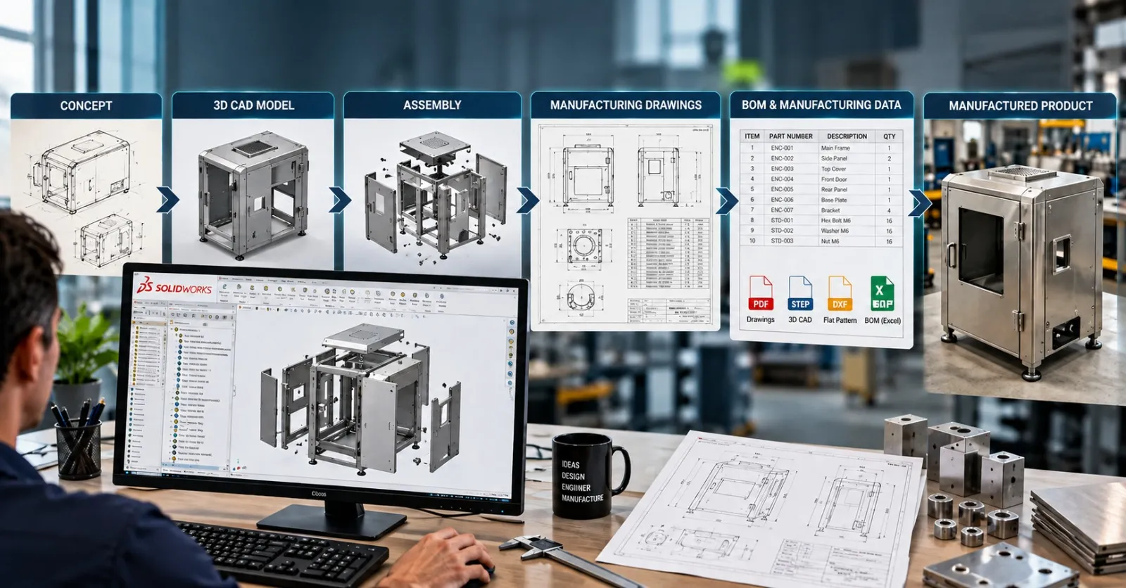
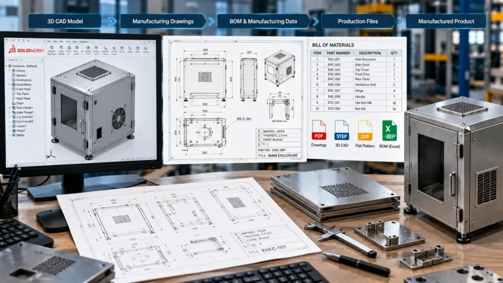
Concept → 3D CAD Model → Detailed Parts → Assembly → Design Validation → DFM Review → Manufacturing Drawings → BOM → Production Data
Depending on the product, the workflow may also include sheet metal development, weldments, surface modeling, configurations, tolerance definition, FEA, rendering, and CAD automation.
For example, a manufacturer developing a new industrial enclosure may start with overall dimensions and functional requirements. The engineering team then develops the enclosure as a 3D SolidWorks model, defines sheet metal features, adds mounting components, checks assembly clearances, prepares flat patterns and production drawings, and finally generates the required manufacturing data.
This makes the CAD model more than a visual representation. It becomes part of the product’s engineering definition.
1. Start With the Product Concept
Every product design project begins with requirements.
These requirements may come from:
- A hand sketch
- Existing 2D drawings
- Customer specifications
- Reference products
- Industrial design concepts
- Physical prototypes
- Product photographs
- Engineering calculations
- Functional requirements
- Existing CAD data
At this stage, the focus should be on understanding what the product needs to do, rather than immediately creating highly detailed geometry.
Important questions include:
- What is the primary function of the product?
- What loads or operating conditions will it experience?
- What are the overall dimensional constraints?
- Which materials are suitable?
- How will the product be manufactured?
- How will components be assembled?
- Which components require purchased hardware?
- Does the product need multiple sizes or configurations?
- What maintenance or service access is required?
Answering these questions early can prevent major redesign later.
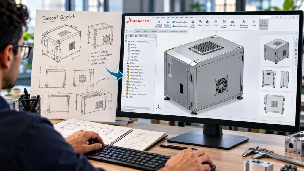
2. Build the Initial 3D CAD Concept
Once the requirements are understood, the concept can be translated into a 3D CAD model.
In SolidWorks, the initial model may use:
- Sketches
- Extrusions
- Revolves
- Sweeps
- Lofts
- Fillets
- Chamfers
- Shell features
- Patterns
- Reference geometry
- Surface features
The objective at this stage is to establish the overall product form and engineering architecture.
A good concept model should allow the designer to explore dimensions and relationships without unnecessarily locking the design into a difficult feature structure.
Why Parametric Modeling Matters
One of the key advantages of SolidWorks is parametric modeling.
Instead of creating geometry without relationships, engineers can define dimensions, constraints, equations, and feature relationships that represent the product’s design intent.
For example, changing the overall width of a machine enclosure could automatically update related features when the model has been structured correctly.
This becomes especially valuable when products require frequent design revisions or multiple variants.
SolidWorks configurations can also be used to create different versions of a part or assembly within a single document, including variations in dimensions, components, features, and properties.
For a deeper discussion, see our guide on Parametric Modeling in SolidWorks.
3. Develop Individual Components
After establishing the overall concept, the product can be broken down into individual components.
For a mechanical product, this could include:
- Frames
- Brackets
- Shafts
- Plates
- Covers
- Enclosures
- Handles
- Hinges
- Mounting components
- Fasteners
- Purchased components
Each component should be modeled according to its intended manufacturing process.
For example:
| Component Type | Possible SolidWorks Approach |
|---|---|
| Machined component | Extrude, revolve, hole features, fillets |
| Sheet metal enclosure | Base flange, bends, hems, forming features |
| Welded frame | Weldments and structural members |
| Plastic housing | Solid modeling and/or surfacing |
| Rotational component | Revolved features |
| Complex exterior | Surface modeling |
| Configurable component | Configurations and design tables |
The modeling approach should reflect not only the desired geometry but also how the component will eventually be produced.
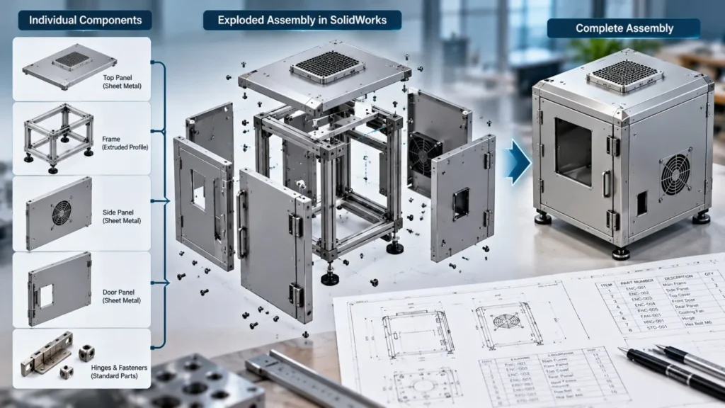
4. Design the Assembly
Individual components must then work together as a complete product.
SolidWorks assemblies allow engineers to position components using mates and establish their intended relationships.
Assembly development helps identify issues such as:
- Component interference
- Insufficient clearances
- Incorrect mounting locations
- Fastener access problems
- Assembly sequence problems
- Component collisions
- Motion limitations
- Service access issues
This is one of the major benefits of developing the product digitally before physical production.
A virtual assembly can expose design problems while changes are still relatively inexpensive.
Assembly Structure Matters
A manufacturing-ready assembly should also have a logical structure.
For example:
Main Assembly
- Frame Subassembly
- Drive Mechanism
- Enclosure
- Control Panel
- Purchased Components
- Fasteners
A structured assembly makes it easier to manage BOMs, revisions, configurations, drawings, and downstream manufacturing documentation.
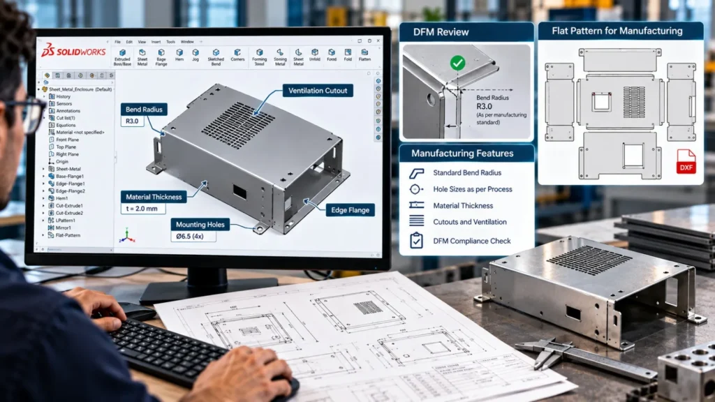
5. Apply Design for Manufacturing Principles
A 3D model can be geometrically correct and still be difficult or expensive to manufacture.
This is where Design for Manufacturing (DFM) becomes important.
DFM considers how the product will actually be produced and assembled.
Depending on the manufacturing process, engineers may evaluate:
- Material availability
- Material thickness
- Bend radii
- Machining access
- Tool accessibility
- Hole sizes
- Weld accessibility
- Fastener access
- Tolerances
- Surface finishes
- Standard component availability
- Manufacturing sequence
- Assembly requirements
For example, a sheet metal enclosure should not only have the correct external dimensions. Its bend radii, flange lengths, reliefs, hole locations, material thickness, and flat pattern should also be suitable for the intended fabrication process.
SolidWorks provides tools and workflows for manufacturability and cost evaluation, including capabilities associated with DFM and manufacturing preparation.
The goal of DFM is not to change the product unnecessarily. It is to identify design decisions that could create manufacturing problems before production begins.
6. Validate the Design Before Manufacturing
Once the product has been modeled and assembled, engineering validation can be performed.
Depending on the application, this may involve:
- Interference Checking: Detects physical clashes between components.
- Motion Analysis: Check whether moving components have the required range of movement.
- Clearance Checking: Verify that components have adequate operating and assembly clearance.
- Mass and Center-of-Gravity Checks: Useful for equipment, rotating assemblies, lifting products, and portable products.
- FEA and Simulation: Finite Element Analysis can be used to investigate stress, deformation, vibration, and other structural behaviors before physical manufacturing.
For products exposed to significant loads, simulation can help identify areas that require design modification before fabrication.
Immersiv Techsphere also supports FEA Simulation in SolidWorks as part of engineering design workflows.
7. Add Materials, Properties, and Engineering Information
A manufacturing-ready CAD model should contain more than geometry.
Engineering information may include:
- Material
- Part number
- Description
- Finish
- Weight
- Revision
- Manufacturer information
- Custom properties
- Configuration-specific information
This information becomes particularly important when CAD data is connected to BOM generation, PDM, ERP, or other engineering systems.
Consistent custom properties can also make downstream documentation and data extraction more reliable.
8. Manage Product Variants With Configurations
Many manufacturers do not produce only one version of a product.
They may have:
- Different sizes
- Different capacities
- Different materials
- Different mounting options
- Different motor selections
- Different enclosure configurations
- Customer-specific variations
Creating separate CAD files for every variation can quickly become difficult to manage.
SolidWorks configurations provide a way to represent multiple variations within a part or assembly document. Design Tables can also be used to manage configuration parameters through Excel-based tables.
For example, a product family could have:
Model A – 500 mm
Model B – 750 mm
Model C – 1000 mm
Rather than rebuilding each model independently, a properly structured parametric model can control the relevant dimensions and features.
This approach can also provide a foundation for future CAD automation and product configurator workflows.
9. Create Manufacturing Drawings
The 3D model is only one part of the manufacturing definition.
Manufacturers often require detailed 2D drawings containing information such as:
- Orthographic views
- Section views
- Detail views
- Dimensions
- Tolerances
- Hole callouts
- Material specifications
- Surface finishes
- Welding information
- Notes
- Revision information
- Drawing numbers
The drawing should communicate the information required by manufacturing, inspection, and assembly teams.
Because SolidWorks drawings are associated with the underlying model, design changes can propagate to related drawing views and documentation. SolidWorks describes this model-to-drawing relationship as part of its approach to production-ready documentation.
Production Drawings Are Not Just Screenshots of the 3D Model
A common mistake is treating manufacturing drawings as a visual output of the CAD model.
A production drawing should answer practical manufacturing questions:
What needs to be made?
What dimensions matter?
What tolerances apply?
What material should be used?
What finish is required?
How should it be fabricated or assembled?
That distinction is critical when converting a concept model into manufacturing-ready CAD.
10. Generate BOM and Manufacturing Data
The next step is preparing the information required downstream.
Depending on the product and manufacturing process, deliverables may include:
- Bill of Materials
- Cut lists
- PDF drawings
- STEP files
- DXF files
- STL files
- Native SolidWorks files
- Assembly documentation
- Inspection information
- Manufacturing notes
For sheet metal products, flat-pattern DXF files may be required for laser cutting or CNC processing.
For machined components, STEP files may be required for manufacturing or CAM workflows.
For assemblies, the BOM provides a structured list of components and quantities.
SolidWorks supports BOMs, weldment cut lists, design tables, and other drawing tables as part of its documentation environment.
11. Prepare the CAD Model for Revision and Change Management
Product development rarely stops after the first approved design.
Engineering teams may receive:
- Customer changes
- Manufacturing feedback
- Supplier changes
- Material substitutions
- Cost-reduction requirements
- Performance improvements
- New product variants
A manufacturing-ready CAD model should therefore be structured for controlled change.
Good modeling practices include:
- Logical feature naming
- Stable references
- Consistent design intent
- Proper configurations
- Standardized custom properties
- Controlled file naming
- Revision tracking
- Structured assemblies
The better the underlying CAD structure, the easier it becomes to maintain the product throughout its lifecycle.
12. Where CAD Automation Fits Into Product Design
Once a company develops a repeatable SolidWorks workflow, automation can reduce repetitive engineering work.
For example, a manufacturer may repeatedly need to:
- Generate similar drawings
- Create multiple configurations
- Export PDFs
- Export DXF files
- Generate STEP files
- Update custom properties
- Generate BOMs
- Rename files
- Extract engineering data
- Prepare manufacturing packages
These activities can potentially be automated using SolidWorks API, VBA, macros, PDM workflows, or custom engineering applications.
Immersiv Techsphere develops SolidWorks API and CAD Automation solutions for repetitive engineering workflows, including drawing generation, BOM automation, configuration management, and manufacturing data extraction.
Our SolidWorks API Automation case study also demonstrates how an automated drawing-generation workflow can reduce repetitive documentation effort.
The important point is that automation should come after the engineering process is understood and standardized.
Automating an inconsistent workflow can simply make an inconsistent process run faster.
A Practical SolidWorks Product Design Workflow
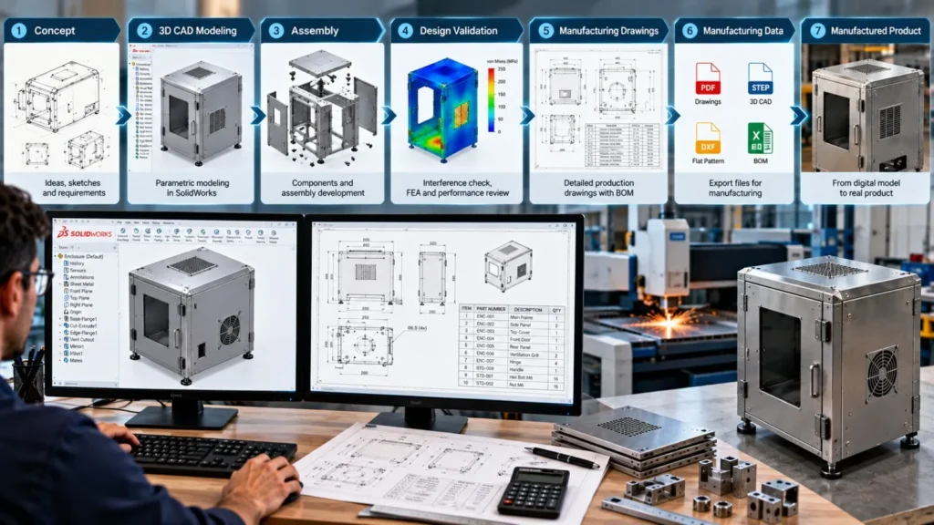
A manufacturing-focused SolidWorks workflow can be summarized as:
- Define Requirements: Understand product function, dimensions, materials, loads, manufacturing process, and customer requirements.
- Create Concept Model: Develop the initial 3D geometry and establish the product architecture.
- Build Parametric Parts: Create components using dimensions, constraints, features, and design intent.
- Develop Assembly: Combine components and check fit, motion, interference, and accessibility.
- Apply DFM Principles: Review the design according to the intended manufacturing process.
- Validate the Design: Perform interference checks, motion checks, calculations, and FEA where appropriate.
- Create Configurations: Develop product variants using configurations and design tables when applicable.
- Prepare Manufacturing Drawings: Add dimensions, tolerances, material specifications, notes, and other production information.
- Generate BOM and Manufacturing Files: Prepare BOMs, PDFs, DXFs, STEP files, cut lists, and other required outputs.
- Review and Release: Verify the complete engineering package before it moves to production.
Common Mistakes in SolidWorks Product Design
Even experienced CAD teams can encounter problems when the model is created primarily for visual appearance rather than manufacturing.
- Modeling Without Design Intent: A model may look correct but become difficult to modify when requirements change.
- Ignoring Manufacturing Processes: Designing geometry without considering machining, fabrication, bending, welding, casting, molding, or assembly can lead to downstream changes.
- Overcomplicated Feature Trees: Unnecessarily complex feature structures can make models difficult to maintain.
- Creating Separate Files for Every Variant: This can increase data duplication and revision-management effort when configurations could be appropriate.
- Treating Drawings as an Afterthought: Missing tolerances, manufacturing notes, material specifications, or critical dimensions can create ambiguity on the shop floor.
- No Standardization: Different engineers using different naming conventions, properties, templates, and modeling practices can create inconsistent engineering data.
- Repeating Manual CAD Tasks: If engineers repeatedly perform the same drawing, BOM, export, or documentation process, the workflow may be a candidate for CAD automation.
What Makes a SolidWorks Model Manufacturing-Ready?
A manufacturing-ready CAD model should satisfy more than geometric accuracy.
A practical checklist includes:
| Area | Manufacturing-Ready Requirement |
|---|---|
| Geometry | Accurate and complete 3D model |
| Design Intent | Logical parametric relationships |
| Materials | Correct material and specification |
| Assembly | Components fit and function correctly |
| DFM | Manufacturing process considered |
| Validation | Design checked for relevant performance requirements |
| Configurations | Product variants properly controlled |
| Drawings | Complete production documentation |
| BOM | Correct components and quantities |
| Manufacturing Data | Required PDF, DXF, STEP or other outputs |
| Revision | Controlled version and change information |
| Automation | Repetitive processes standardized where appropriate |
How Immersiv Techsphere Supports SolidWorks Product Design
At Immersiv Techsphere, we support engineering and manufacturing teams with 3D CAD modeling, mechanical product design, manufacturing drawings, design validation, and CAD automation.
Our workflows can support projects involving:
- Industrial equipment
- Sheet metal products
- Machinery
- Fitness equipment
- Furniture
- Laboratory equipment
- Fabricated products
- Mechanical assemblies
- Custom manufacturing products
Our engineering services can cover the transition from 3D concept to production documentation, including models, assemblies, fabrication drawings, BOMs, and manufacturing data.
For an overview of our broader capabilities, explore our engineering design and CAD automation services.
You can also explore our engineering solutions brochures for additional examples of our design and manufacturing support.
Frequently Asked Questions
Product design in SolidWorks is the process of developing a product using 3D parametric CAD, from initial concept and component modeling through assembly, validation, manufacturing documentation, and production data.
Yes. SolidWorks supports part and assembly modeling, configurations, engineering drawings, BOMs, sheet metal, weldments, and other capabilities used to develop production documentation.
A concept model primarily communicates product form and function. A manufacturing-ready CAD model additionally incorporates detailed geometry, materials, design intent, assembly relationships, manufacturing considerations, tolerances, drawings, BOM information, and required production data.
DFM evaluates whether a design is practical to manufacture using the intended process. It can identify issues related to tolerances, material thickness, bend radii, machining access, welding, assembly, and other manufacturing requirements before production.
Yes. SolidWorks configurations allow multiple variations of parts and assemblies to be managed within a document. Design Tables can also be used to control configuration parameters.
Yes. Repetitive tasks such as drawing generation, BOM extraction, file export, custom property updates, and configuration-related workflows can potentially be automated using SolidWorks API, VBA, macros, PDM, or custom applications.
Depending on project requirements, engineering teams may generate native SolidWorks files, PDF drawings, STEP, DXF, STL, BOMs, cut lists, and other manufacturing documentation.
Conclusion
Product design in SolidWorks is not simply the process of creating a 3D model. It is the development of a structured digital product definition that can move from engineering concept toward physical manufacturing.
The strongest workflows connect:
Concept → Parametric CAD → Assembly → DFM → Validation → Drawings → BOM → Manufacturing Data
When this workflow is structured correctly, design changes become easier to manage, product variants can be controlled more systematically, and manufacturing teams receive clearer engineering information.
For companies with repetitive product families or documentation-heavy engineering processes, the next step can be connecting SolidWorks product design with CAD automation, configurations, PDM, and product configurators.
The result is a more connected engineering workflow, from the first concept model to the manufacturing-ready CAD package.
Have a Project in Mind?
Need help with 3D animation, industrial visualization, HSE training animation, or product visualization? Tell us about your project and our team will get back to you.