

Table of Contents
Introduction
Oil & Gas projects involve complex engineering systems where mechanical equipment, piping, structural supports, access platforms, and instrumentation must work together within a defined space. Even when individual components are designed correctly, conflicts between these components can create costly problems during fabrication, assembly, and installation.
3D CAD Design for Oil & Gas helps engineering teams identify potential design conflicts before they become physical problems. By coordinating equipment interfaces, piping routes, structural clearances, and maintenance access within a 3D environment, engineers can review how different components interact before manufacturing begins.
For equipment manufacturers, EPC contractors, and engineering consultancies, effective 3D CAD coordination can improve design communication, reduce avoidable revisions, and support more predictable project execution.
This article explains how 3D CAD coordination works, which design conflicts it can help identify, and how a structured engineering workflow can reduce rework across Oil & Gas projects.
What Is 3D CAD Coordination in Oil & Gas Engineering?
3D CAD coordination is the process of reviewing and aligning mechanical equipment, piping, structural components, and other project elements within a shared or coordinated digital representation.
Instead of evaluating each component independently, engineers examine how the components fit together and interact within the available installation space.
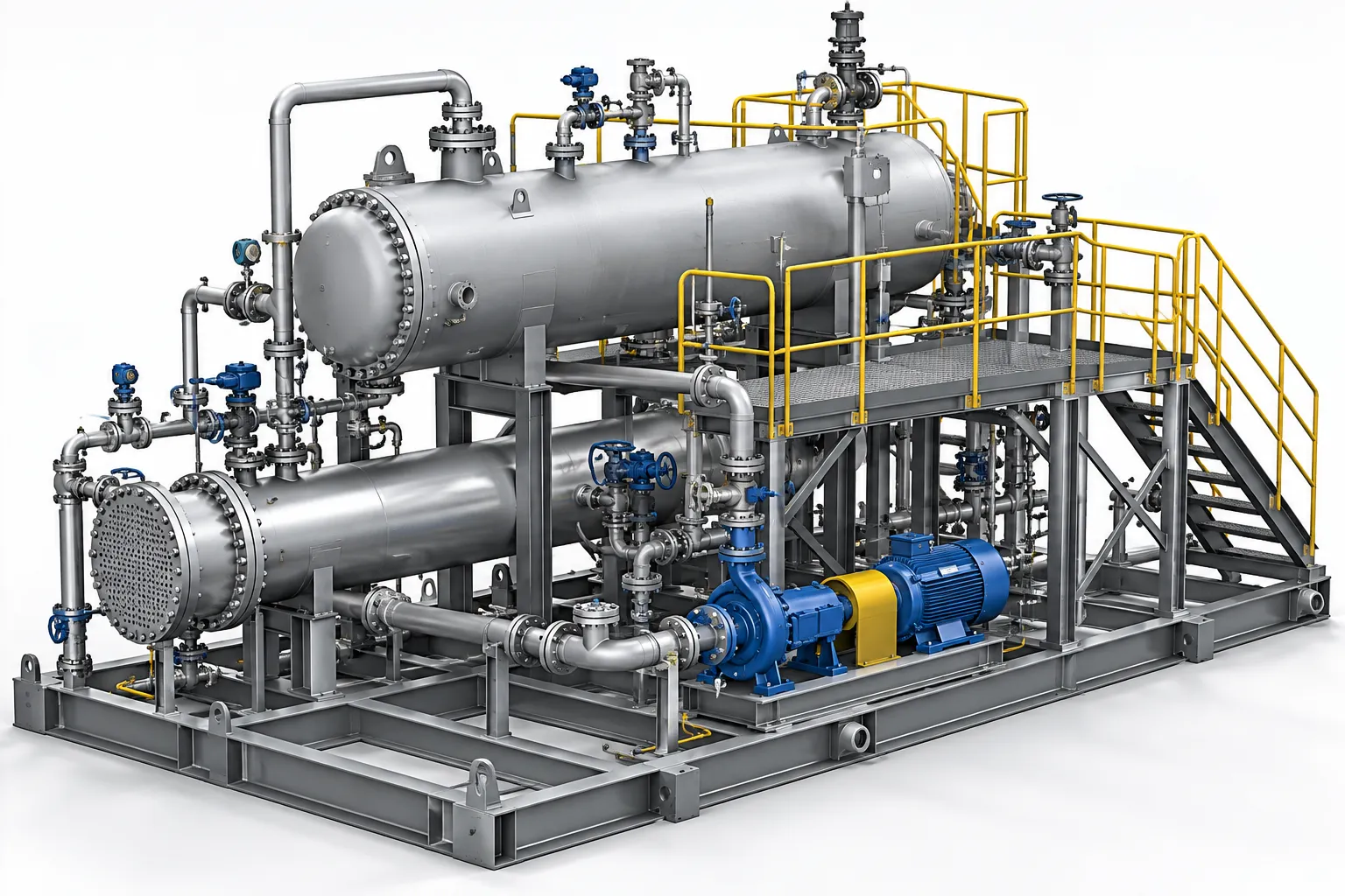
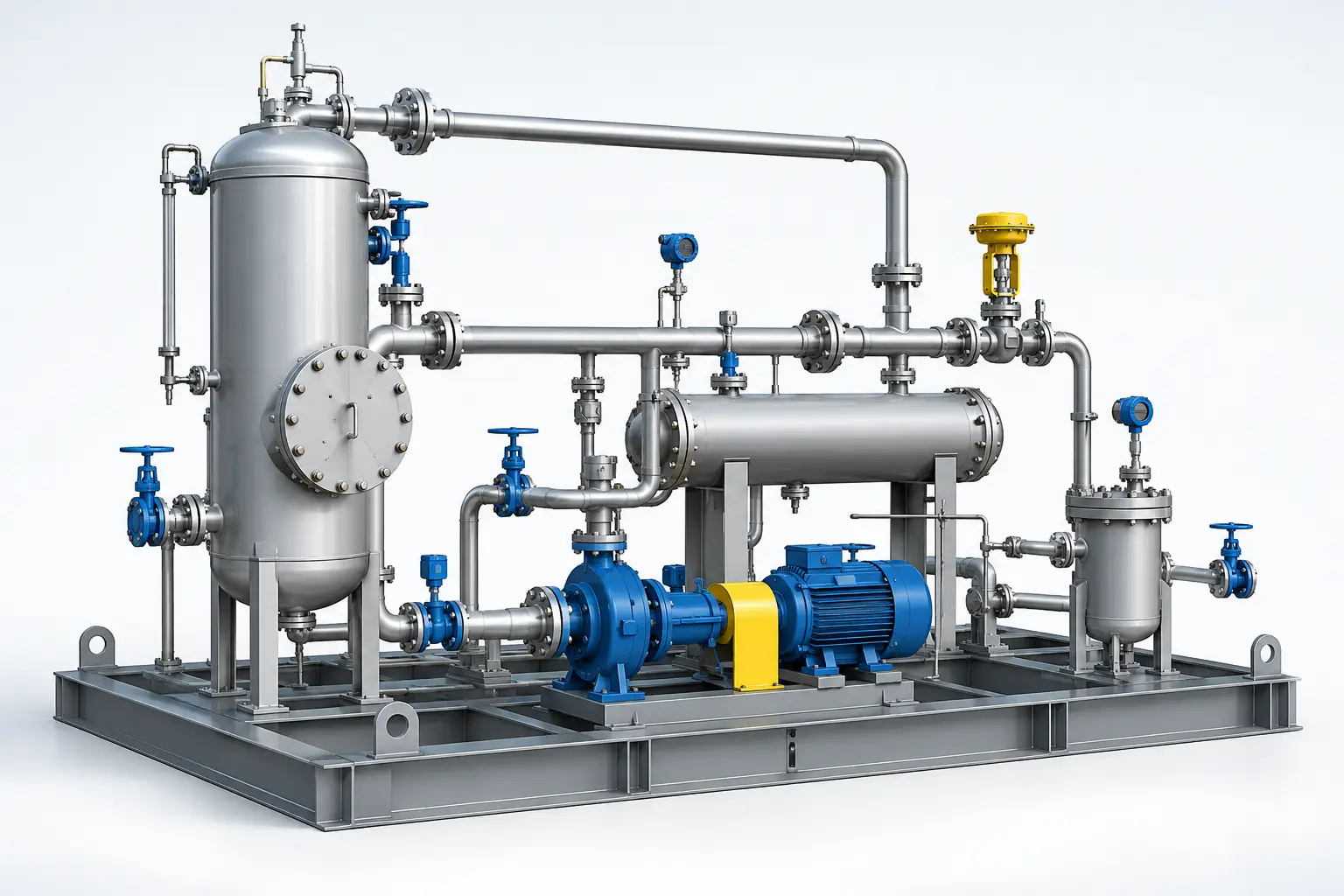
For example, a process equipment skid may contain:
- Pumps, motors, and process equipment
- Inlet and outlet piping
- Valves, flanges, and pipe supports
- Structural frames and mounting plates
- Platforms, ladders, and access points
- Instrumentation and maintenance interfaces
- Equipment nozzle positioning.
- Flange alignment.
- Motor and pump mounting interfaces.
- Structural support connections.
- Maintenance and installation clearances.
Each component may satisfy its individual design requirements, yet the complete assembly can still contain interference or accessibility issues.
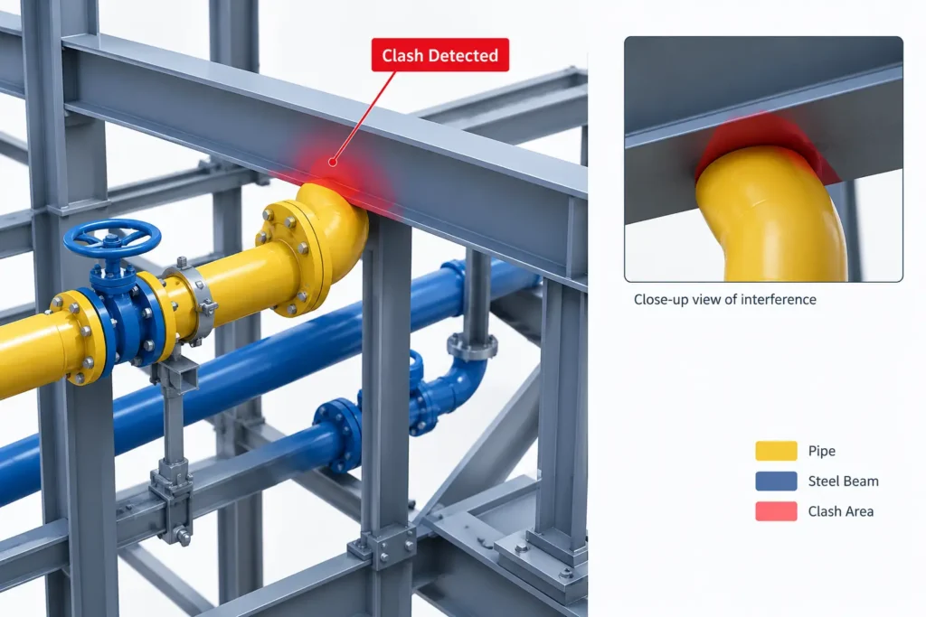
A pipe may intersect a structural beam. A valve may be positioned too close to a handrail. A motor may have insufficient clearance for removal. A mounting interface may not align with the supporting frame.
3D CAD coordination helps reveal these relationships before fabrication or installation, allowing engineers to investigate and resolve design issues while changes are generally easier to manage.
Why Does Design Rework Occur in Oil & Gas Projects?
Design rework often occurs when engineering information is incomplete, individual disciplines work with inconsistent references, or component interfaces are not reviewed early enough.
Several common situations can contribute to these problems.
1. Equipment and piping interface conflicts
Equipment nozzle locations, flange orientations, and connection dimensions must align with the intended piping arrangement. If these interfaces are based on outdated vendor drawings or incorrect assumptions, the resulting connections may require modification.
2. Piping and structural interference
Piping routes must account for structural members, supports, platforms, and other installed components. A route that appears feasible in a two-dimensional drawing may create a physical conflict when evaluated within the complete 3D assembly.
3. Insufficient maintenance access
Oil & Gas equipment requires access for inspection, servicing, component replacement, and routine operation. If these requirements are not considered during design, engineers may need to reposition equipment, modify supports, or revise access arrangements later.
4. Inconsistent design revisions
Mechanical, piping, and structural teams may work on separate models and drawings. When a change in one discipline is not communicated or reflected in related design information, downstream components can become misaligned.
5. Incomplete manufacturing information
A coordinated 3D model must be supported by appropriate drawings, dimensions, material information, and revision details. Discrepancies between the model and released documentation can lead to fabrication errors even when the original design intent is correct.
These challenges show why design accuracy involves more than producing geometrically correct components. It also requires coordination between the components, the disciplines, and the engineering information used downstream.
How 3D CAD Design for Oil & Gas Helps Reduce Rework
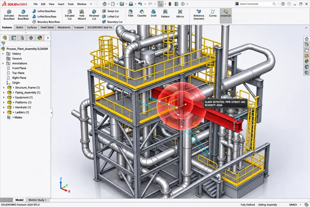
1. Identifying design clashes before fabrication
One of the most practical benefits of 3D CAD coordination is the ability to inspect component relationships before physical production begins.
Engineers can review equipment assemblies and compare the positions of piping, structural members, supports, platforms, and other components.
Potential issues include:
- Pipes intersecting beams or equipment housings
- Flanges occupying the same space as structural supports
- Valves interfering with handrails or adjacent components
- Mounting plates conflicting with frame members
- Fasteners or fittings lacking installation clearance
Where compatible models and suitable software are available, automated clash detection can help identify geometric overlaps. Engineers can then review the results, determine whether each conflict is genuine, and revise the relevant design.
Not every detected overlap represents an actual problem. Some intersections may be intentional, and clearance requirements can extend beyond simple geometric interference. Engineering review therefore remains essential.
For more information, Autodesk explains how 3D model coordination and clash detection support design reviews before construction.
2. Improving equipment interface coordination
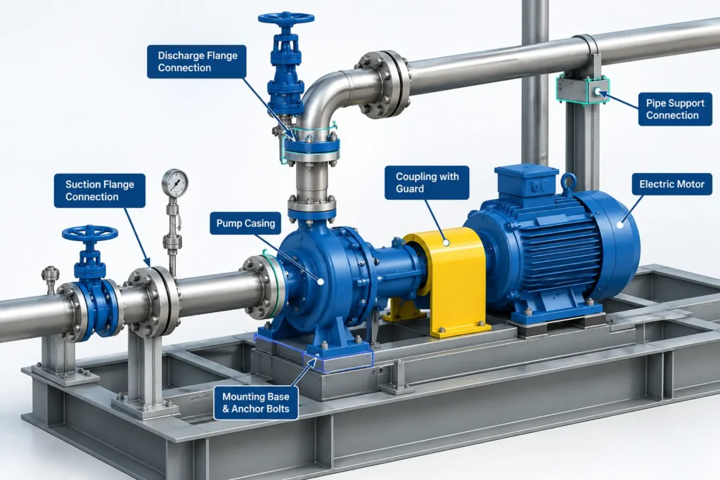
Equipment interfaces connect individual components into a functional assembly. These interfaces may include pipe nozzles, flanges, mounting holes, base plates, support connections, and equipment envelopes.
During 3D CAD design, engineers can check whether the interfaces align with the surrounding components and available installation space.
For example, a pump package mounted on a fabricated skid may require coordination between the pump base, motor position, suction piping, discharge piping, and supporting steelwork.
A change in the pump model or nozzle position can affect several connected components. Reviewing these relationships within the assembly helps engineers identify which parts or drawings may require updates.
Accurate interface information is particularly important when equipment is sourced from different vendors or designed by separate engineering teams.
3. Coordinating piping routes with structural components
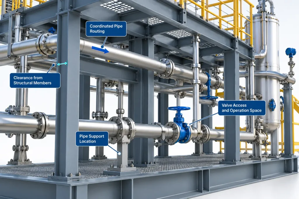
Piping systems must navigate around equipment, beams, columns, platforms, and other obstacles while maintaining the requirements defined by the project engineers.
A coordinated 3D model provides a clearer view of these relationships than isolated component drawings alone.
Engineers can evaluate:
- Available routing space
- Pipe and fitting clearances
- Valve positioning and operating access
- Locations of pipe supports
- Potential conflicts with structural members
- Access around flanges and connection points
- Clearance for flange bolting and tightening.
- Space required for pipe insulation, where applicable.
- Pipe support installation and maintenance accessibility.
Piping coordination also needs to consider project-specific requirements for thermal movement, flexibility, support loads, and maintenance. A visually clear route does not automatically establish that the piping system is mechanically adequate.
When mechanical and structural models are reviewed together, conflicts can be addressed before they lead to repeated fabrication changes or site modifications.
4. Checking maintenance and installation access
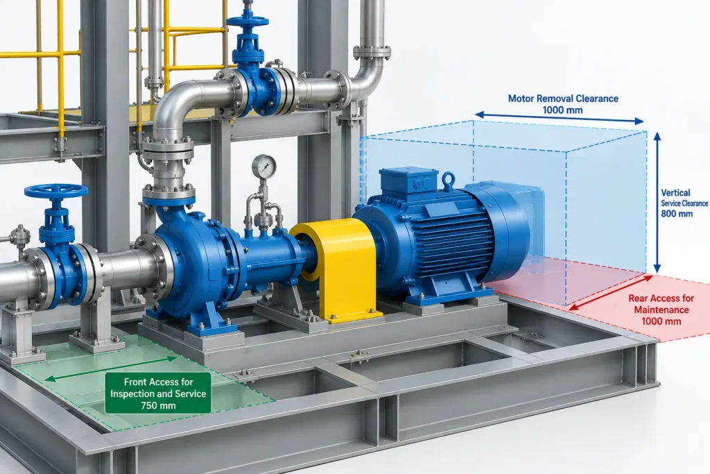
A component can fit within a 3D assembly and still be difficult to operate, inspect, or replace.
For example, a valve may be installed between two structural members with insufficient space for operation. A pump may have adequate static clearance but lack the space needed to remove its motor. A filter housing may be inaccessible without dismantling nearby components.
3D CAD coordination allows engineers to review these practical requirements during design development.
Depending on the equipment, the review may include:
- Space required to remove motors, pumps, and other components
- Access to valves, instruments, and inspection points
- Clearance for tools and fasteners
- Operator access to controls and isolation points
- Routes for moving replacement components
- Space around platforms, ladders, and handrails
- Filter housing removal.
These checks should use the applicable project requirements, equipment vendor recommendations, and maintenance procedures.
Considering access early can reduce the need to redesign supports, reposition equipment, or modify platforms after fabrication has started.
5. Coordinating mechanical and structural design
Mechanical and structural engineering decisions are closely connected in skid-mounted and packaged equipment.
The mechanical arrangement determines equipment positions, connection locations, and certain interface loads. The structural arrangement provides the supporting frame, mounting plates, beams, and connections needed to accommodate the equipment.
If either discipline changes its design without updating the related interfaces, conflicts may arise.
For example, increasing the size of a mounting plate may affect nearby piping clearance. Moving a structural cross-member may improve support arrangements but obstruct access to a valve. Changing equipment spacing may affect the overall skid dimensions.
A coordinated 3D CAD workflow helps teams review these dependencies together.
It also provides a common visual reference for design reviews, making it easier to discuss proposed changes and understand their impact on adjacent components.
Structural adequacy, connection design, and load capacity must still be evaluated using appropriate engineering methods. Geometric coordination alone does not verify structural performance.
6. Maintaining consistency between models and drawings
A design change is useful only when the relevant engineering information is updated and communicated correctly.
When the 3D model, manufacturing drawings, assembly documentation, and bill of materials contain inconsistent information, fabrication teams may work from conflicting instructions.
A structured CAD workflow helps engineers identify affected components and review the associated documentation before release.
Useful checks include:
- Confirming that drawing dimensions reflect the approved model
- Reviewing mounting and interface details after revisions
- Verifying part numbers and component quantities
- Updating revision information and affected documents
- Checking that the released drawing package matches the approved design
For projects involving repeated equipment configurations, CAD automation can support consistent drawing generation, BOM extraction, and document exports. These activities can reduce repetitive manual work, but generated outputs still need appropriate validation.
Explore CAD automation services for engineering workflows to understand how repetitive design and documentation tasks can be streamlined.
A Practical 3D CAD Coordination Workflow for Oil & Gas Projects
A consistent coordination workflow helps engineering teams identify issues systematically instead of relying only on final-stage inspections.
Step 1: Collect and verify engineering inputs
Gather the available equipment datasheets, vendor models, piping layouts, interface dimensions, structural references, and applicable project requirements.
Confirm the revision status and reliability of the source information before using it for detailed coordination.
Step 2: Develop or integrate the 3D models
Create or incorporate the relevant mechanical equipment, piping components, supports, and structural elements. Depending on the project, these may be developed in one CAD environment or exchanged between compatible systems.
Coordinate model units, origin points, reference geometry, and component locations to avoid alignment errors.
Step 3: Review interfaces and clearances
Check equipment connections, mounting points, pipe routes, structural members, and maintenance spaces. Use defined project clearances and equipment-specific requirements rather than relying only on visual judgment.
Step 4: Identify and resolve conflicts
Record identified clashes and interface issues. Assign each issue to the responsible discipline, agree on the required change, and update the affected components.
Review the updated arrangement to confirm that resolving one conflict has not introduced another.
Step 5: Update engineering documentation
Revise affected drawings, dimensions, BOMs, and related documentation. Maintain revision traceability so that downstream teams can identify the approved design information.
Step 6: Conduct a final coordination review
Review the updated assembly and its supporting documentation before release. Confirm that major interfaces, identified clashes, access requirements, and relevant project checks have been addressed.
This workflow creates a traceable path from engineering inputs to coordinated models and manufacturing information.
What Should Engineers Check During a 3D CAD Coordination Review?
A coordination checklist can help standardize design reviews across equipment packages and projects.
| Review area | Key checks |
|---|---|
| Equipment interfaces | Nozzle positions, flange alignment, mounting holes, connection dimensions, Anchor bolts, nozzle alignment |
| Piping | Routing conflicts, fittings, valves, support locations, required clearances, Flange access, insulation clearance |
| Structural components | Beam and column interference, mounting interfaces, access around connections |
| Maintenance access | Component removal space, tool access, inspection points, operating access |
| Installation | Assembly sequence, lifting and handling requirements, installation space |
| Documentation | Drawing revisions, dimensions, BOM consistency, interface details |
| Engineering validation | Applicable structural, piping, equipment, and project-specific checks |
The precise scope of the review depends on the equipment, project phase, design responsibilities, and applicable standards.
How Immersiv Techsphere Supports 3D CAD Design for Oil & Gas
Immersiv Techsphere supports engineering and manufacturing teams with mechanical CAD design, 3D modeling, technical drafting, manufacturing documentation, and CAD automation.
For Oil & Gas equipment projects, a structured CAD workflow can help organize equipment geometry, review component interfaces, coordinate fabricated assemblies, and prepare engineering information for downstream manufacturing activities.
Depending on the project scope, support may include:
- 3D mechanical equipment modeling and assembly development
- Review of equipment interfaces and surrounding components
- Fabrication-oriented CAD models and technical drawings
- Mechanical and structural interface coordination
- Manufacturing drawing and BOM preparation
- CAD automation for repetitive design and documentation tasks
The objective is to help teams work with consistent engineering information and identify design issues before they create avoidable downstream changes.
Learn more about Oil & Gas equipment design, 3D modeling, and manufacturing drawings.
Frequently Asked Questions
3D CAD coordination is the process of reviewing mechanical equipment, piping, structural components, and related interfaces within a coordinated digital model to identify design conflicts and verify spatial relationships before fabrication or installation.
It helps engineers identify clashes, incorrect interfaces, insufficient clearances, and maintenance access problems during design development. Resolving these issues before fabrication can reduce avoidable component modifications, drawing revisions, and site rework.
Depending on the model detail and review method, engineers can identify piping and beam interference, equipment overlaps, conflicting mounting arrangements, restricted valve access, and other geometric conflicts between modeled components.
Piping and structural components share limited installation space. Coordinating them helps engineers review pipe routes, support positions, structural clearances, and equipment connections before fabrication and installation.
A 3D model can help review access to valves, instruments, motors, pumps, and removable components. Engineers must assess the applicable service clearances, operating requirements, maintenance procedures, and equipment vendor recommendations.
No. It supports geometric coordination and design reviews but does not replace required piping stress analysis, structural calculations, pressure equipment design checks, or other engineering validation required by the project.
Relevant services include 3D mechanical modeling, assembly development, interface reviews, technical drafting, manufacturing documentation, and CAD automation. The required scope depends on project deliverables and the responsibilities of each engineering discipline.
Conclusion
Rework in Oil & Gas projects can result from equipment interface conflicts, piping and structural interference, insufficient maintenance access, inconsistent revisions, and gaps in manufacturing documentation.
3D CAD Design for Oil & Gas helps address these challenges by allowing engineers to review component relationships before fabrication and installation. When combined with clear engineering requirements, coordinated design reviews, accurate drawings, and controlled revisions, it can improve design communication and reduce avoidable downstream changes.
However, a coordinated model is only one part of an effective engineering process. Project-specific calculations, structural and piping checks, equipment requirements, and applicable codes must still be verified by the responsible engineering team.
For Oil & Gas manufacturers and engineering teams, the goal is to move beyond designing individual components and establish a coordinated workflow in which equipment, structures, interfaces, and documentation work together.
Planning an Oil & Gas equipment design project? Contact Immersiv Techsphere to discuss your 3D CAD modeling, mechanical design, technical drafting, and engineering documentation requirements.
Have a Project in Mind?
Need help with 3D animation, industrial visualization, HSE training animation, or product visualization? Tell us about your project and our team will get back to you.