


Table of Contents
Introduction
Designing equipment for the oil and gas industry requires more than creating an accurate 3D model. Engineering teams must translate process requirements, mechanical interfaces, material specifications, fabrication requirements, tolerances, and project documentation into a design that can ultimately be manufactured, inspected, assembled, and maintained.
A well-structured oil and gas equipment design workflow connects these stages, from 3D CAD modeling and assembly development in SolidWorks to detailed manufacturing drawings and documentation.
For engineering teams handling repeated equipment variants, the workflow can go one step further. SolidWorks API and CAD automation can automate repetitive modeling, configuration, drawing, BOM, and documentation tasks, helping reduce manual engineering effort while maintaining consistency.
This article explains how the process works and where engineering automation can add value.
What Is Oil and Gas Equipment Design?
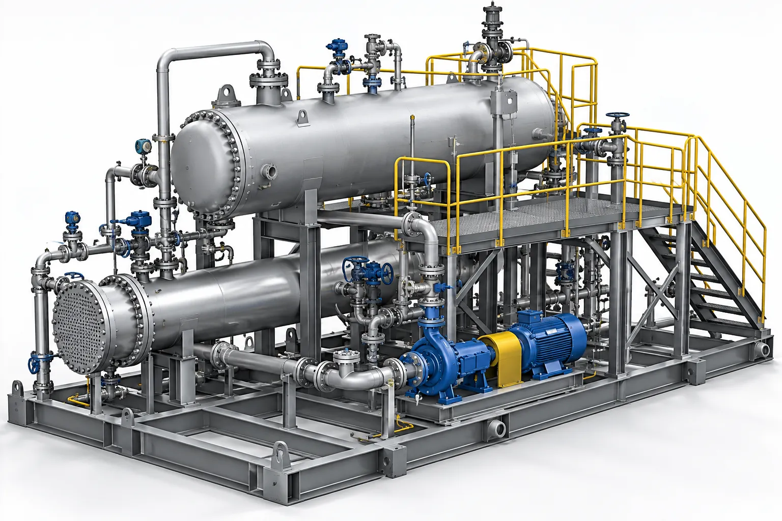
Oil and gas equipment design involves the development of mechanical equipment and supporting components used across upstream, midstream, downstream, refining, processing, storage, and related industrial operations.
Depending on the project, equipment may include:
- Process skids
- Pressure-related equipment
- Storage and handling equipment
- Pump and compressor packages
- Heat exchanger assemblies
- Filtration systems
- Valve assemblies
- Pipe support structures
- Equipment frames and bases
- Access platforms and ladders
- Structural supports
- Enclosures and guards
- Fabricated mechanical assemblies
The design process typically has to account for more than geometry. Engineers must consider load conditions, material selection, manufacturability, connections, accessibility, maintenance requirements, tolerances, and applicable project or industry requirements.
This makes CAD modeling an important part of a larger engineering process rather than an isolated drafting activity.
From Engineering Requirements to a 3D CAD Model
A typical equipment design project begins with engineering inputs rather than a blank CAD screen.
Inputs may include:
- Equipment specifications
- Existing 2D drawings
- P&IDs
- Equipment layouts
- Vendor data
- Datasheets
- Reference models
- Design calculations
- Material specifications
- Interface dimensions
- Customer standards
- Manufacturing constraints
The first objective is to convert these inputs into a clear mechanical design definition.
For example, when developing a fabricated equipment skid, the engineer may need to establish:
- Overall equipment envelope
- Equipment mounting locations
- Structural frame dimensions
- Nozzle or pipe connection locations
- Maintenance access
- Lifting points
- Foundation or mounting interfaces
- Component clearances
- Service access
- Fabrication requirements
Once the engineering intent is established, the design can be developed as a structured 3D SolidWorks model.
Why SolidWorks Is Useful for Oil and Gas Equipment Design
SolidWorks provides a parametric 3D CAD environment suitable for developing mechanical parts, assemblies, weldments, configurations, and detailed drawings.
For oil and gas equipment projects, a structured SolidWorks model can help engineers visualize how individual components fit together before fabrication.
A typical assembly may contain:
Components → Subassemblies → Main Equipment Assembly → Manufacturing Documentation
For example:
Equipment Skid
→ Structural frame
→ Pump assembly
→ Motor
→ Piping components
→ Valves
→ Supports
→ Mounting brackets
→ Access platform
→ Guards
The advantage of modeling the complete assembly is that potential issues can be identified earlier.
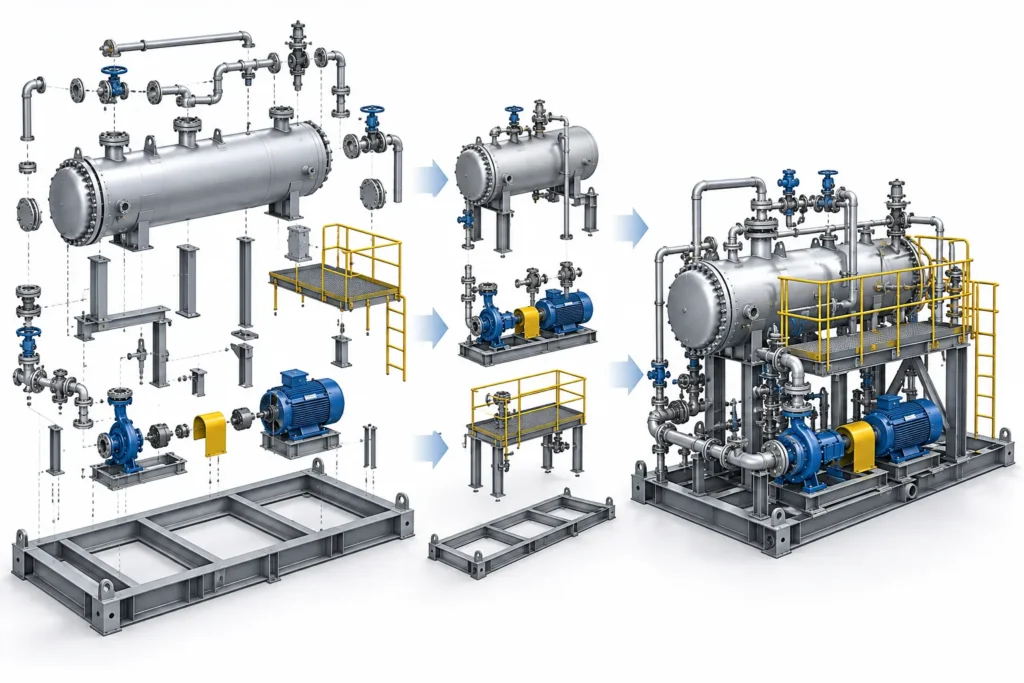
Design reviews can check:
- Component interference
- Insufficient clearances
- Accessibility
- Mounting conflicts
- Fastener access
- Equipment envelope
- Assembly sequence
- Serviceability
- Structural interfaces
This is particularly useful when several components must occupy a limited equipment footprint.
Step 1: Develop the 3D Equipment Model
The first major CAD stage is creating the equipment geometry.
Depending on the equipment, the model may contain a combination of:
- Machined components
- Welded structures
- Sheet metal parts
- Pipes and fittings
- Purchased components
- Fasteners
- Guards
- Brackets
- Platforms
- Structural members
For fabricated equipment, weldments and structural members can be particularly useful for developing frames and supports.
A good model should also preserve design intent.
Instead of creating geometry that only looks correct, the model should be structured so that important dimensions and relationships can be modified efficiently.
For example, if an equipment frame needs to change from 2,000 mm to 2,200 mm wide, dependent components should update predictably rather than requiring extensive manual remodeling.
This is where parametric modeling in SolidWorks becomes valuable.
Read more about Parametric Modeling in SolidWorks
Step 2: Build the Equipment Assembly
Once individual components are modeled, they are brought together into the equipment assembly.
Assembly modeling helps establish the physical relationship between components.
For example, a process skid assembly may need to coordinate:
- Pump position
- Motor position
- Pipe routing
- Valve access
- Structural supports
- Instrument locations
- Equipment mounting points
- Maintenance clearances
The assembly also becomes an important reference for creating manufacturing and fabrication documentation.
A structured assembly hierarchy can make large projects easier to manage.
Example assembly structure
Main Equipment Assembly
- Skid Frame
- Base Members
- Cross Members
- Mounting Plates
- Pump Package
- Motor
- Piping Assembly
- Valve Assembly
- Instrumentation Supports
- Access Platform
- Safety Guard
This approach makes it easier to isolate components, manage revisions, generate BOM information, and prepare manufacturing documentation.
Step 3: Design for Manufacturability
A 3D model is not automatically a manufacturing-ready design.
Before drawings are released, the design should be reviewed against the intended manufacturing process.
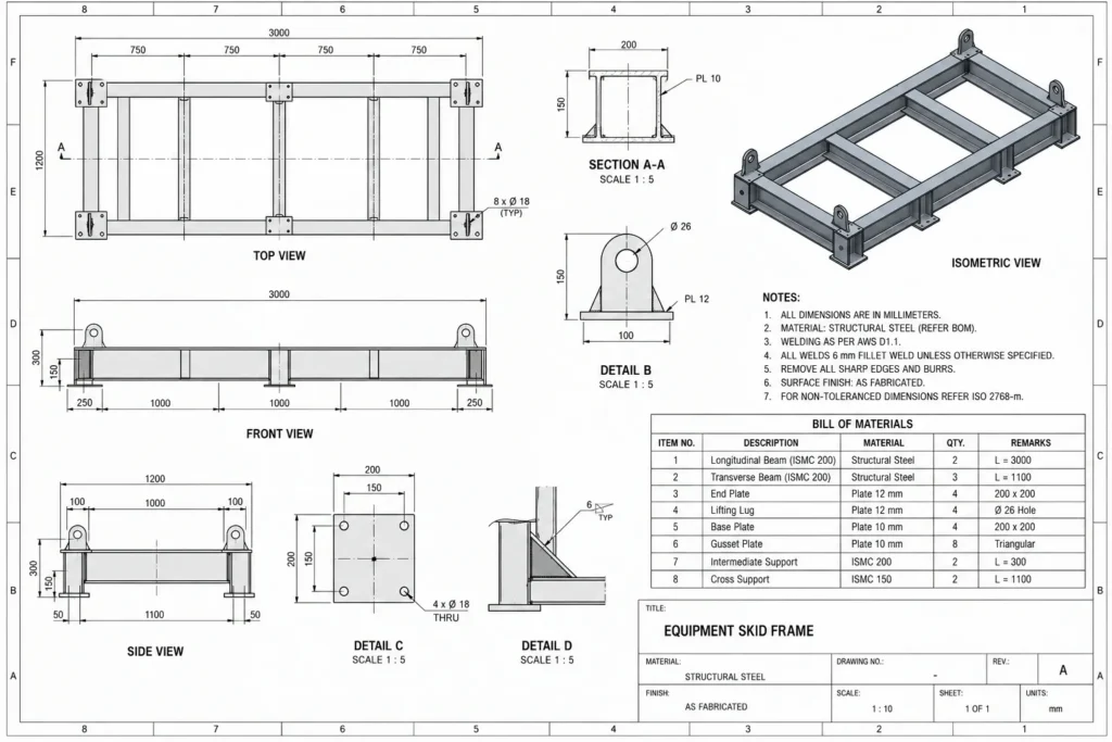
For fabricated oil and gas equipment, this may involve reviewing:
- Weld accessibility
- Plate thickness
- Structural member selection
- Machining requirements
- Hole accessibility
- Bend requirements
- Fastener installation
- Assembly sequence
- Material availability
- Component tolerances
- Surface requirements
- Inspection requirements
For example, a bracket may be geometrically correct but difficult to weld because the weld area cannot be accessed properly.
Similarly, two components may technically fit together while leaving insufficient space for a wrench, fastener, or maintenance activity.
Design for Manufacturing (DFM) therefore needs to be considered during modeling rather than after the drawings are completed.
Step 4: Apply Materials and Engineering Information
Material information is another important part of an equipment model.
Depending on the project, components may require information such as:
- Material grade
- Thickness
- Part number
- Description
- Manufacturer
- Finish
- Weight
- Revision
- Project number
This information can be stored using custom properties and other model metadata.
Proper metadata becomes particularly useful when engineering outputs need to be generated repeatedly.
For example, the same model information can potentially support:
3D Model → Drawing → BOM → PDF → Manufacturing Package
rather than requiring engineers to enter the same information repeatedly.
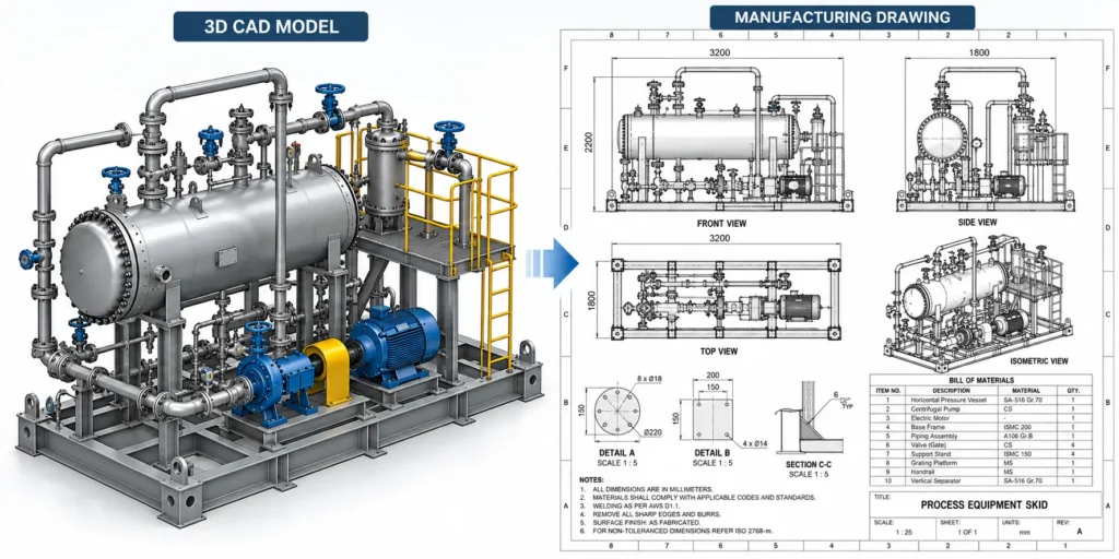
Step 5: Create Manufacturing Drawings
The manufacturing drawing is where the 3D design is translated into information that fabrication and production teams can use.
A typical drawing package may include:
Part drawings
Used for individual manufactured components.
They can contain:
- Dimensions
- Tolerances
- Material
- Surface finish
- Hole details
- Threads
- Section views
- Detail views
- Manufacturing notes
Assembly drawings
Used to communicate how components fit together.
They may include:
- Assembly views
- Component identification
- BOM
- Reference dimensions
- Weld information
- Assembly notes
Fabrication drawings
For welded structures, frames, supports, and similar components, fabrication drawings may communicate:
- Member sizes
- Cut lengths
- Plate dimensions
- Hole locations
- Weld symbols
- Joint details
- Material specifications
- Assembly references
Why Drawing Accuracy Matters
A manufacturing drawing is not simply a 2D version of the 3D model.
It is an engineering communication document.
The drawing needs to communicate the information required to manufacture and inspect the component correctly.
One important area is Geometric Dimensioning and Tolerancing (GD&T).
ASME describes Y14.5 as a key standard for establishing and interpreting GD&T, helping communicate design intent, form, fit, function, and interchangeability.
For suitable applications, GD&T can define requirements for:
- Position
- Flatness
- Straightness
- Perpendicularity
- Parallelism
- Profile
- Runout
- Datum references
The goal is not to apply as many tolerances as possible. The goal is to specify the tolerances necessary for the component to perform its intended function and be manufactured and inspected effectively.
ASME Y14.5 Dimensioning and Tolerancing
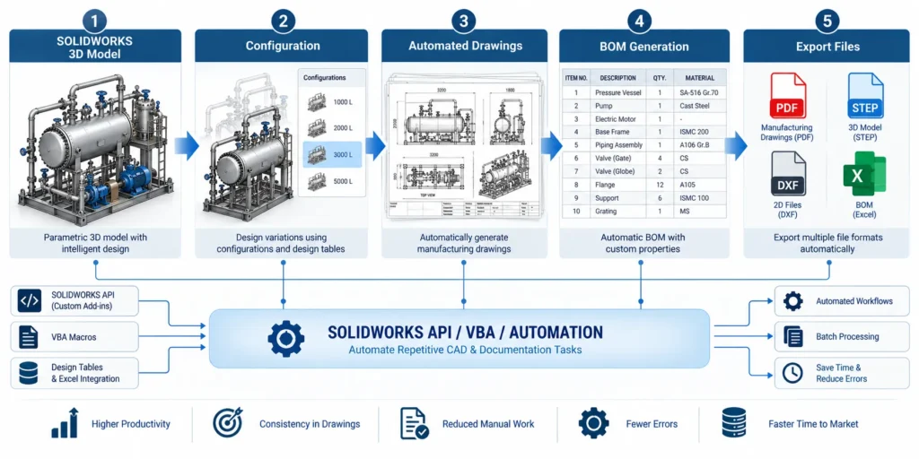
Step 6: Generate BOM and Manufacturing Documentation
For equipment containing many components, the Bill of Materials (BOM) becomes an important deliverable.
A BOM can provide information such as:
| Item | Description | Part Number | Material | Quantity |
|---|---|---|---|---|
| 1 | Base Frame | FR-001 | Structural Steel | 1 |
| 2 | Mounting Plate | MP-001 | Carbon Steel | 4 |
| 3 | Equipment Support | SP-001 | Carbon Steel | 4 |
| 4 | Guard Assembly | GA-001 | Steel | 1 |
| 5 | Fastener Set | FS-001 | As Specified | 1 |
The exact structure depends on the company’s engineering and manufacturing standards.
A well-organized SolidWorks assembly can help connect BOM information to the CAD model and drawing environment.
This reduces the risk of discrepancies between:
3D model ↔ BOM ↔ Drawing ↔ Manufacturing documentation
Step 7: Review the Complete Design Package
Before release, the engineering team should perform a final review of the model and drawings.
A useful review can cover four areas.
1. Geometry
Does the 3D model represent the intended equipment?
2. Assembly
Do all components fit and interface correctly?
3. Manufacturing
Can the components actually be fabricated, machined, welded, and assembled as documented?
4. Documentation
Do drawings, BOMs, model metadata, and other outputs agree?
This final cross-check is important because a design can contain errors even when the individual CAD operations appear correct.
Where SolidWorks Automation Fits Into the Workflow
For organizations designing a single piece of equipment occasionally, manual CAD workflows may be sufficient.
The situation changes when engineers repeatedly create similar equipment.
Consider a manufacturer that produces several equipment configurations with changes to:
- Overall dimensions
- Capacity
- Motor size
- Pump selection
- Pipe connection locations
- Frame dimensions
- Mounting arrangements
- Component quantities
If engineers manually update every model, drawing, BOM, and document, repetitive work can quickly become a significant part of the engineering workload.
This is where SolidWorks automation can provide an additional layer of productivity.
The SolidWorks API provides programmatic access to SolidWorks functionality and supports automation using technologies including VBA, VB.NET, C#, C++, and SolidWorks macros.
What Can Be Automated in SolidWorks?
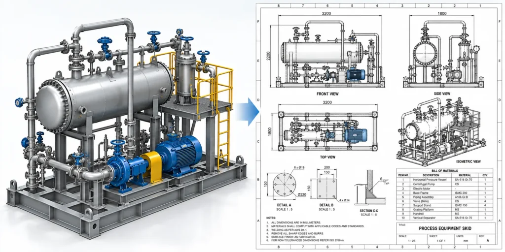
Automation does not have to mean fully automating the entire design process.
In many engineering environments, the best opportunities are repetitive tasks with clearly defined rules.
Drawing Automation
Repeated drawing tasks can potentially be automated, including:
- Creating drawing documents
- Inserting drawing views
- Updating predefined templates
- Populating title blocks
- Adding standard notes
- Applying custom properties
- Exporting drawings
- Managing drawing sheets
SolidWorks provides API interfaces for drawing operations, including access to drawing views and other drawing-document functions.
BOM Automation
Automation can help with:
- BOM generation
- BOM formatting
- Part-number population
- Custom-property extraction
- Document naming
- Manufacturing package preparation
Configuration Automation
For products with controlled variations, SolidWorks Design Tables can manage multiple configurations using parameters such as dimensions, feature states, components, mates, and configuration properties.
This can be useful when an equipment family follows defined engineering rules.
Batch Export
A custom automation tool can potentially process multiple files and generate required outputs such as:
- PDF drawings
- STEP files
- DXF files
- BOM data
- Other project documentation
The exact automation scope depends on the company’s workflow, file structure, SolidWorks version, and engineering rules.
Example: Automating an Oil and Gas Equipment Design Workflow
Consider a manufacturer producing several sizes of a standardized process skid.
The manual workflow might look like:
Customer Requirement
↓
Engineer selects configuration
↓
Modify SolidWorks model
↓
Update assembly
↓
Update drawings
↓
Check BOM
↓
Export PDF
↓
Export STEP/DXF where required
↓
Prepare manufacturing package
With a rules-based automation workflow, the process can potentially become:
Configuration Parameters
↓
SolidWorks Model Updates
↓
Assembly & Configuration Update
↓
Drawing Generation
↓
BOM Generation
↓
Manufacturing File Export
↓
Standardized Documentation Package
The engineer remains responsible for engineering decisions and validation, while the software handles repetitive operations that follow predefined rules.
That distinction is important.
Automation should reduce repetitive CAD work, not replace engineering judgment.
Building a Scalable SolidWorks Automation Workflow
A successful automation project usually starts by identifying repetitive engineering operations.
For example:
“Every time we receive an equipment order, engineers spend several hours updating the same drawing templates, BOM information, and export files.”
That is a much stronger automation opportunity than trying to automate an entire design process without first defining the engineering rules.
At Immersiv Techsphere, our CAD automation approach focuses on understanding the existing workflow, identifying repetitive tasks, and developing tools around defined engineering processes.
Potential solutions can include:
- SolidWorks macros
- SolidWorks API development
- VBA automation
- Drawing automation
- BOM automation
- Configuration automation
- Template standardization
- Batch file processing
- Documentation automation
- Workflow integration
Explore SolidWorks CAD Automation Services
Common Challenges in Oil and Gas CAD Projects
1. Incomplete Engineering Inputs
Design teams may receive a combination of PDFs, legacy drawings, sketches, vendor models, spreadsheets, and incomplete dimensions.
The engineer must establish what information is authoritative before modeling.
2. Frequent Design Changes
Customer requirements, equipment selections, interfaces, and project specifications can change during development.
A well-structured parametric model makes controlled revisions easier.
3. Large Assemblies
Oil and gas equipment can contain numerous purchased and fabricated components.
Proper assembly organization, naming conventions, configurations, and references become important.
4. Documentation Rework
Manual drawing creation and repetitive document preparation can consume significant engineering time.
This is one of the areas where automation can provide measurable productivity benefits.
5. Manufacturing Communication
A technically correct model still needs clear manufacturing documentation.
Dimensions, tolerances, materials, weld information, notes, BOMs, and revision information must communicate the manufacturing intent clearly.
Best Practices for Oil and Gas Equipment CAD Modeling
- Start with engineering requirements: Define functional and interface requirements before detailed modeling.
- Build with design intent: Use meaningful parameters, relationships, and feature structures rather than creating geometry that is difficult to modify.
- Separate purchased and manufactured components: This makes BOM management and procurement workflows easier to organize.
- Use standardized templates: Standard drawing templates, title blocks, properties, and notes improve documentation consistency.
- Consider manufacturing during design: Check fabrication, machining, welding, assembly, inspection, and maintenance requirements before releasing drawings.
- Control configurations carefully: For equipment families, use configurations and structured design rules where appropriate.
- Automate repetitive operations: If engineers repeatedly perform the same CAD or documentation task, evaluate whether it can be automated.
- Validate before release: Automation can improve consistency, but engineering review remains essential before manufacturing release.
How Immersiv Techsphere Supports Oil and Gas Equipment Design
Oil and gas is one of the industries supported by Immersiv Techsphere, with capabilities spanning engineering design, drafting, CAD automation, and industrial visualization.
Our engineering workflow can support projects involving:
- 3D mechanical modeling
- Equipment assemblies
- Fabrication-oriented CAD
- Manufacturing drawings
- Industrial drafting
- BOM documentation
- Design modifications
- SolidWorks modeling
- CAD process optimization
- SolidWorks API automation
- Engineering documentation automation
For oil and gas projects specifically, our drafting capabilities include 2D and 3D drafting for piping, equipment layouts, and structural detailing.
Explore Oil & Gas Drafting and Engineering Services
The workflow can also be extended into automation when a client has recurring equipment designs or documentation tasks.
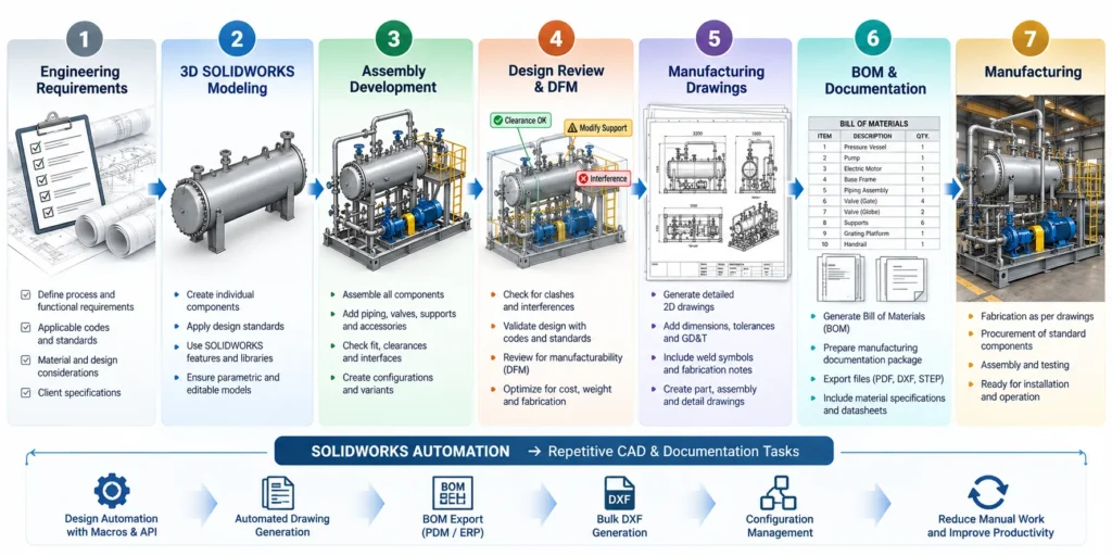
From 3D Model to Manufacturing: Why the Complete Workflow Matters
The real value of an oil and gas CAD workflow is not the 3D model alone.
The model should become the foundation for downstream engineering outputs.
A structured workflow can connect:
Engineering Requirements
→ 3D SolidWorks Modeling
→ Assembly Development
→ Design Review
→ DFM Considerations
→ Manufacturing Drawings
→ BOM
→ PDF / STEP / DXF and Other Outputs
→ Manufacturing
When repetitive stages are supported by SolidWorks automation, engineering teams can move toward a more standardized and scalable process.
This is particularly valuable for manufacturers producing equipment families where many projects follow similar engineering rules.
Frequently Asked Questions
SolidWorks is one option for mechanical 3D CAD modeling, assemblies, configurations, weldments, and manufacturing drawings. The appropriate software depends on project requirements, customer standards, data-exchange requirements, and the type of equipment being designed.
Yes. SolidWorks can be used for mechanical components, equipment assemblies, structural frames, weldments, piping-related mechanical layouts, guards, supports, and manufacturing documentation. The design still needs to comply with the applicable project specifications, engineering calculations, codes, and standards.
Manufacturing drawings provide the dimensional and technical information required to fabricate, machine, weld, inspect, or assemble components. They can include dimensions, tolerances, materials, weld symbols, notes, section views, details, and BOM information.
Yes. The SolidWorks API supports automation and customization of SolidWorks functionality, including drawing operations.
Depending on the workflow, automation can be developed for drawing generation, BOM creation, custom properties, configurations, and repetitive file-export tasks.
SolidWorks API automation uses programmatic interfaces to control and customize SolidWorks. It can be implemented through technologies such as VBA, VB.NET, C#, C++, and SolidWorks macros.
Automation can reduce repetitive manual operations, standardize outputs, improve consistency, and allow engineers to spend more time on engineering decisions rather than repetitive CAD administration.
The review should consider geometry, interfaces, dimensions, tolerances, materials, weld details, manufacturability, assembly requirements, BOM accuracy, revision information, and applicable project or industry requirements.
Conclusion
Oil and gas equipment design is a connected engineering process that extends from 3D CAD modeling to manufacturing documentation.
SolidWorks can provide the foundation for developing parametric parts, assemblies, configurations, and detailed engineering drawings. But the effectiveness of the workflow depends on how well the CAD model, engineering information, manufacturing requirements, and documentation are connected.
For organizations handling repetitive equipment designs, SolidWorks API automation, macros, and configuration-driven workflows can take the process further by automating tasks such as drawing creation, BOM generation, file exports, and documentation.
The objective is not simply to create CAD models faster.
It is to build a more consistent, manufacturing-focused, and scalable engineering workflow—from the first design requirement through the final manufacturing package.
Learn About Immersiv Techsphere’s CAD Automation Solutions
Have a Project in Mind?
Need help with 3D animation, industrial visualization, HSE training animation, or product visualization? Tell us about your project and our team will get back to you.