
Table of Contents
Introduction
Product design is rarely a one-time process. A component that is approved today may need to be modified tomorrow because of changes in dimensions, customer requirements, manufacturing constraints, material selection, cost targets, or assembly conditions.
The challenge is not simply making a design change. The real challenge is making that change quickly, accurately, and without manually rebuilding related geometry, features, assemblies, and drawings.
This is where parametric modeling in SolidWorks becomes valuable.
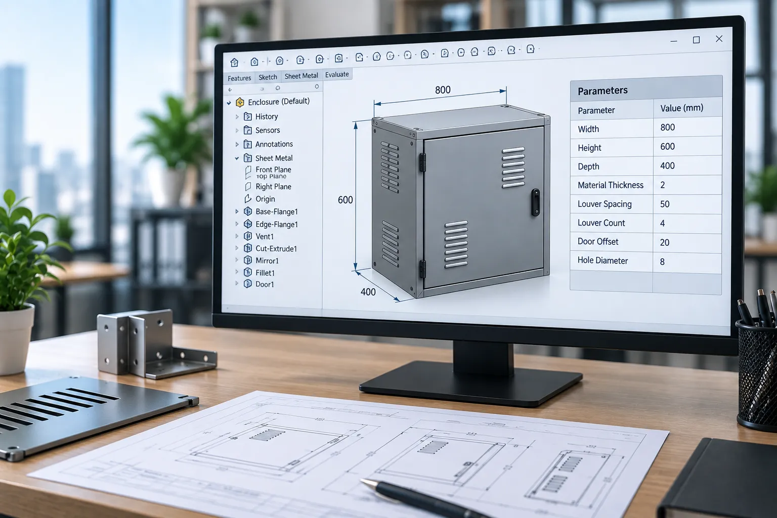
SolidWorks uses a parametric, feature-based approach to 3D CAD modeling. Designers can define relationships between dimensions, sketches, features, parts, and assemblies so that changes to one design parameter can automatically propagate through the model.
For manufacturers and engineering teams handling multiple product variants, frequent design revisions, or repetitive CAD work, parametric modeling can help create a more controlled and efficient product development workflow. These capabilities can be extended further through SolidWorks automation solutions that automate repetitive design and engineering tasks.
In this article, we explain what parametric modeling is, how it works in SolidWorks, how it simplifies engineering changes, and how businesses can extend it further through SolidWorks API automation and custom CAD automation solutions.
What Is Parametric Modeling?
Parametric modeling is a CAD modeling method in which the geometry of a part is controlled by defined parameters, dimensions, constraints, equations, and relationships.
Instead of creating independent geometry that must be manually edited, a parametric model stores the logic used to create the design.
For example, a rectangular mounting plate may be controlled by parameters such as:
- Length
- Width
- Thickness
- Hole diameter
- Hole spacing
- Edge distance
- Number of holes
If the length of the plate changes, related features can update based on the defined relationships.
A parametric model therefore contains not only the final 3D geometry but also the design intent behind that geometry.
Simple Example of a Parametric Relationship
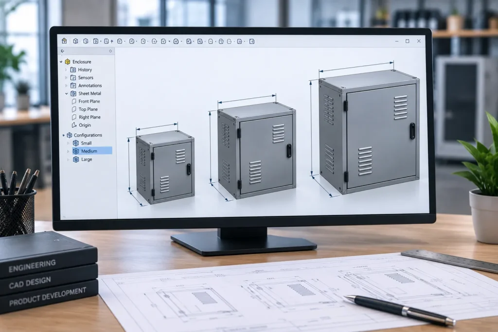
Consider a sheet metal enclosure with the following parameters:
- Width = 500 mm
- Height = 300 mm
- Depth = 200 mm
- Vent hole spacing = 50 mm
If the enclosure width needs to increase from 500 mm to 650 mm, a properly designed parametric model can update related sketches, features, hole patterns, and dependent geometry automatically.
Without parametric relationships, the designer may need to manually edit multiple features and verify whether all associated geometry has been updated correctly.
This ability to control geometry through parameters is one of the main reasons parametric CAD modeling is widely used in modern product design and engineering.
How Parametric Modeling Works in SolidWorks
In SolidWorks, parametric models are typically created using a combination of:
- Sketch dimensions
- Geometric relations
- Feature dimensions
- Parent-child relationships
- Equations
- Global variables
- Configurations
- Design tables
- Assembly mates and references
These elements work together to define how a model behaves when a design parameter changes.
1. Sketch Dimensions and Relations
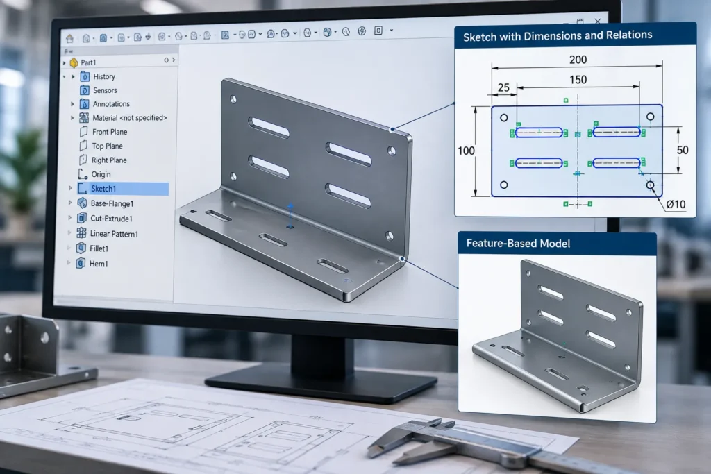
Most SolidWorks models begin with a 2D sketch.
The sketch can include dimensions and geometric relationships such as:
- Horizontal
- Vertical
- Parallel
- Perpendicular
- Concentric
- Tangent
- Equal
- Symmetric
These relations define the position and behavior of sketch entities.
For example, instead of manually positioning four mounting holes, a designer can define equal spacing and symmetry relationships. When the plate dimensions change, the hole positions can update according to the established design logic.
2. Feature-Based Modeling
SolidWorks models are created using features such as:
- Extrudes
- Cuts
- Revolves
- Fillets
- Chamfers
- Shells
- Patterns
- Holes
- Sweeps
- Lofts
Each feature can depend on previous geometry and parameters.
For example, a cut feature may reference an existing face, while a pattern may depend on the dimensions of a base feature.
This creates a structured feature history that allows engineers to modify the model by changing the parameters that control individual features.
3. Equations and Global Variables
SolidWorks allows dimensions to be linked using equations and global variables.
For example:
Plate Width = Product Width – 20 mm
or:
Hole Spacing = Plate Width / 4
This allows design changes to propagate based on predefined mathematical relationships.
Instead of manually changing multiple dimensions, an engineer can modify a single global variable and allow related dimensions to update automatically.
This is particularly useful for product families and configurable designs where multiple dimensions follow defined engineering rules.
4. Configurations and Design Variants
Many manufacturers create similar products in different sizes or specifications.
For example, a company may offer:
- Small enclosure
- Medium enclosure
- Large enclosure
Rather than building three completely separate models, SolidWorks configurations can be used to manage different parameter values within a product family.
Configurations can control:
- Dimensions
- Feature suppression
- Component selection
- Materials
- Custom properties
- Assembly structure
When combined with parametric relationships, configurations can help engineers manage product variants more efficiently.
Why Product Design Changes Become Difficult Without Parametric Modeling
Engineering changes often affect more than one dimension.
A change in a product’s width, for example, may also impact:
- Hole locations
- Internal components
- Mounting brackets
- Sheet metal bends
- Fastener locations
- Assembly clearances
- Manufacturing drawings
- Bill of Materials
- CNC or DXF data
When these elements are not properly connected, engineers may need to manually update each area of the design.
This increases the possibility of:
- Missed dimensions
- Incorrect feature updates
- Assembly interference
- Drawing inconsistencies
- Incorrect manufacturing data
- Rework during production
A well-structured parametric model reduces this manual dependency by defining relationships between the design elements.
The goal is not simply to make models easier to edit. The goal is to create a more predictable engineering change process.
How Parametric Modeling Simplifies Product Design Changes
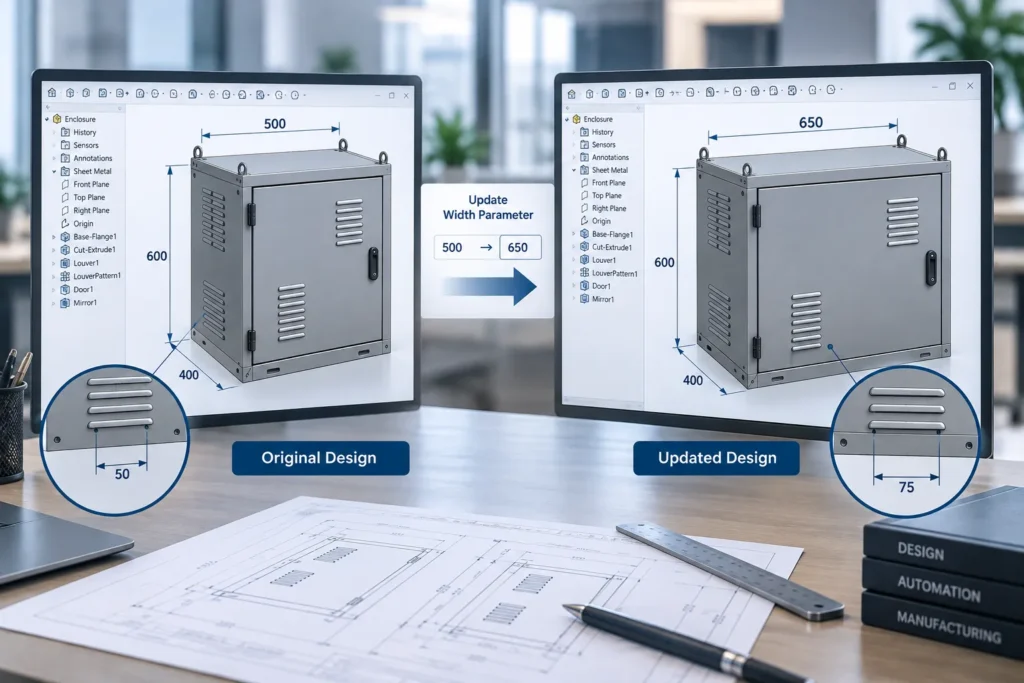
One of the biggest advantages of parametric modeling is that a design can be controlled through key dimensions and variables.
For example, an engineer may change:
Overall Length: 1000 mm → 1200 mm
Depending on the model structure, this change can automatically affect:
- Feature locations
- Hole spacing
- Pattern instances
- Internal supports
- Dependent sketches
- Assembly components
The engineer does not need to manually redraw every affected feature.
This can significantly reduce the time required to create product revisions.
2. Preserve Engineering Design Intent
A 3D model should represent more than the final shape of a product.
It should also communicate how the product is intended to behave when dimensions change.
For example, consider four mounting holes that must always remain:
- 25 mm from the side edges
- Symmetrical around the centerline
- Equal in diameter
If these relationships are defined in the parametric model, changing the overall size of the part does not require manually repositioning each hole.
The model preserves the original engineering logic.
This is commonly referred to as capturing design intent.
3. Reduce Repetitive CAD Editing
Manufacturers often create similar parts repeatedly.
A design engineer may receive requests such as:
- Increase the width by 100 mm
- Change the hole diameter
- Add two additional mounting points
- Create a new size variant
- Modify the frame dimensions
- Change material thickness
When a parametric model is properly structured, many of these changes can be performed by modifying existing parameters rather than rebuilding the model.
For companies handling frequent custom orders or product variations, this can reduce repetitive CAD work.
4. Improve Consistency Across Product Variants
Product families often share a common design structure.
For example, an industrial equipment manufacturer may offer the same machine in multiple capacities.
The core design may remain the same while parameters such as the following change:
- Length
- Width
- Capacity
- Number of components
- Motor size
- Structural member dimensions
Parametric modeling allows these relationships to be incorporated into the model.
Combined with SolidWorks configurations, design tables, or automation, this approach can support faster generation of product variants while maintaining design consistency.
5. Simplify Design Updates Across Assemblies
A product is often made up of multiple parts and assemblies.
When one component changes, other components may also need to be updated.
For example, increasing the size of a base frame may affect:
- Mounting plates
- Brackets
- Covers
- Fasteners
- Internal components
Parametric relationships and assembly references can help maintain these dependencies.
However, engineers must carefully manage external references and design dependencies to avoid creating unnecessarily complex or fragile models.
A well-planned parametric structure is therefore important for both flexibility and model stability.
6. Support Faster Drawing Updates
Engineering drawings are typically linked to the underlying 3D model.
When a parametric model is updated and the geometry changes correctly, associated drawing views and dimensions can also update based on the model.
This can reduce the amount of manual drawing modification required after a design change.
The result is a more connected workflow between:
3D CAD Model → Assembly → Engineering Drawing → Manufacturing Documentation
This connection can help reduce inconsistencies between design and documentation.
Example: Parametric Modeling of a Custom Industrial Product
Consider a manufacturer that produces industrial equipment with customized frame sizes.
Each customer may require different:
- Overall dimensions
- Mounting locations
- Component capacities
- Material thicknesses
- Access panel sizes
Without a parametric approach, engineers may need to:
- Copy an existing model.
- Modify individual sketches.
- Update features.
- Reposition components.
- Modify the assembly.
- Update drawings.
- Generate manufacturing files.
- Perform design verification.
This process can become repetitive when similar changes are required for every customer order.
This approach is especially useful for products that require frequent dimensional changes, such as sheet metal enclosures and cabinets, where dimensions, hole patterns, cutouts, and bend features may vary between product variants.
With a structured parametric model, key dimensions can instead be controlled using defined parameters.
For example:
| Parameter | Example |
|---|---|
| Overall Length | 1000 mm |
| Overall Width | 600 mm |
| Overall Height | 800 mm |
| Frame Profile Size | 50 mm |
| Mounting Hole Diameter | 12 mm |
| Hole Edge Distance | 30 mm |
When the product dimensions change, related geometry can update according to the design rules defined within the model.
The workflow can be extended further using SolidWorks automation to automatically generate specific product variants, drawings, BOMs, DXF files, or other engineering outputs.
Parametric Modeling vs Direct Modeling
Parametric modeling and direct modeling are different approaches to modifying CAD geometry.
Parametric Modeling
In parametric modeling, geometry is controlled through:
- Features
- Dimensions
- Constraints
- Equations
- Relationships
Changes are generally made by modifying the parameters or features that define the model.
Direct Modeling
Direct modeling allows geometry to be modified by directly manipulating faces and features.
For example, an engineer may move, resize, or delete a face without necessarily modifying the original feature history.
When Parametric Modeling Is Useful
Parametric modeling is particularly useful when:
- Product designs require frequent revisions.
- Multiple product variants are required.
- Engineering rules control the design.
- Dimensions are interdependent.
- Models need to be reused for future projects.
- Repetitive design changes occur.
Direct modeling can be useful when modifying imported geometry or making quick geometric changes where feature history is not available or practical.
In many engineering workflows, both approaches can be used depending on the design requirements.
Best Practices for Building Strong Parametric SolidWorks Models
Parametric modeling provides the most value when the model is structured carefully.
1. Identify the Key Design Parameters
Before building the model, identify which dimensions are most likely to change.
These may include:
- Overall length
- Width
- Height
- Material thickness
- Hole size
- Component spacing
- Number of repeated features
These dimensions can become the primary control parameters for the model.
2. Define Relationships Instead of Repeating Dimensions
Avoid manually entering the same dimension in multiple locations when those dimensions should remain connected.
Use:
- Relations
- Equations
- Global variables
This can reduce the number of independent dimensions that engineers must manually maintain.
3. Build Models Around Functional Design Intent
A feature should reflect the functional purpose of the product whenever possible.
For example, mounting holes should be positioned based on functional reference geometry rather than arbitrary sketch coordinates.
This makes future design changes easier to manage.
4. Use Meaningful Global Variables
Global variables should have clear names.
For example:
- Overall_Length
- Overall_Width
- Material_Thickness
- Hole_Diameter
- Mounting_Spacing
Clear naming improves model readability and makes it easier for other engineers to understand and modify the design.
5. Avoid Unnecessary External References
External references can help connect related parts, but excessive dependencies can make a model more difficult to manage.
Use external references strategically and document the design structure where required.
6. Plan for Product Variants
If a product is expected to have multiple versions, plan the parametric structure early.
Consider whether variations should be managed using:
- Configurations
- Design tables
- Separate models
- DriveWorks
- Custom SolidWorks automation
The right approach depends on the number of variants, design complexity, and level of customization.
Extending Parametric Modeling with SolidWorks Automation
Parametric modeling becomes even more powerful when combined with automation.
For example, a company may have a parametric model that requires engineers to manually enter new values for every project.
A custom automation solution can potentially:
- Read input values from a form, spreadsheet, ERP system, or database.
- Open the SolidWorks model.
- Update parameters and dimensions.
- Rebuild the model.
- Generate the required configuration.
- Create engineering drawings.
- Update custom properties.
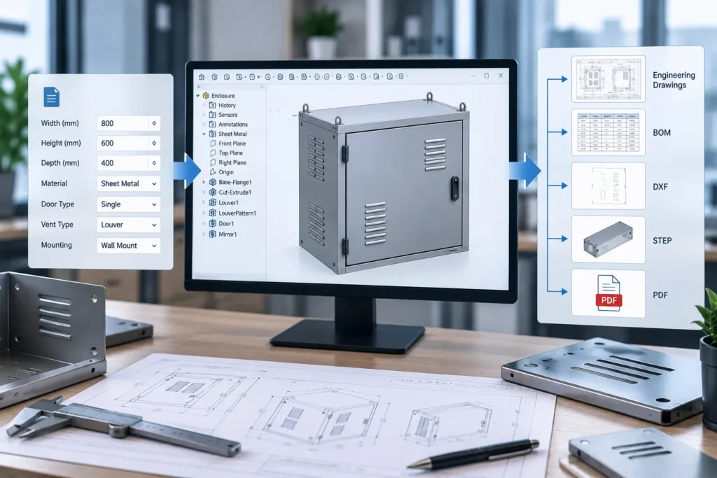
- Export DXF, PDF, STEP, or other required files.
- Save the project using predefined naming rules.
This creates a more automated engineering workflow.
Example Workflow
Customer Requirements → Input Parameters → Parametric SolidWorks Model → Automated Model Update → Drawing and Documentation Generation → DXF / PDF / STEP / Manufacturing Data
This approach can reduce repetitive manual tasks and help engineering teams process recurring design changes more efficiently.
How SolidWorks API Automation Can Support Parametric Product Design
For organizations that repeatedly create customized products, standard parametric modeling may still require significant manual interaction.
The SolidWorks API can be used to create custom automation tools based on specific engineering workflows.
For example, a custom application may allow an engineer or non-CAD user to enter:
- Product dimensions
- Material specifications
- Component options
- Customer requirements
- Manufacturing parameters
The automation can then update the corresponding parametric model.
Depending on the workflow, SolidWorks API automation can also help automate:
- Part generation
- Assembly creation
- Configuration management
- Drawing generation
- Custom property updates
- BOM creation
- DXF export
- PDF generation
- STEP file generation
- File naming and organization
This can be particularly valuable for companies that manufacture engineered-to-order, configure-to-order, or highly customized products.
Common Industries That Can Benefit from Parametric CAD Modeling
Parametric modeling can be useful across a wide range of engineering and manufacturing industries.
- Industrial Equipment Manufacturing: Manufacturers can manage equipment with variable dimensions, capacities, and component configurations.
- Sheet Metal Fabrication: Sheet metal parts with different sizes, hole patterns, cutouts, and bend dimensions can be created from structured parametric models.
- Material Handling Equipment: Conveyors, platforms, storage systems, and custom handling equipment often require dimensional variations based on site or customer requirements.
- Machinery and Special Purpose Equipment: Machine designs can contain repeatable engineering logic while allowing dimensions and configurations to change for individual projects.
- Lab and Technical Furniture Manufacturing: Workstations, cabinets, tables, frames, and modular systems may require frequent dimensional customization.
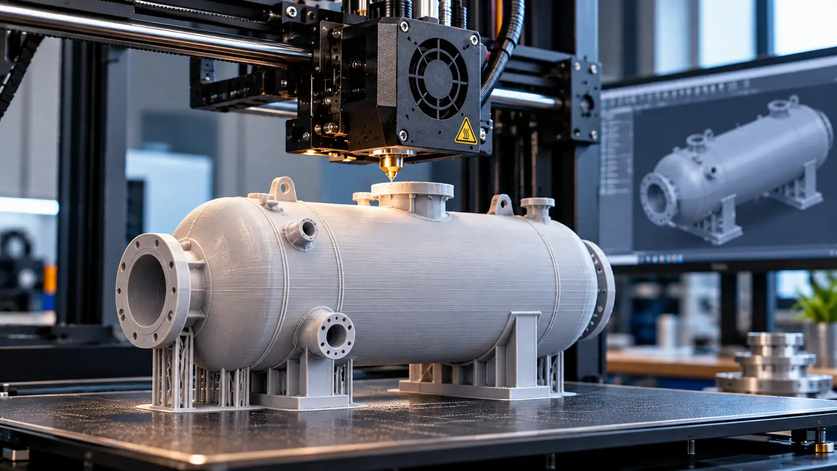
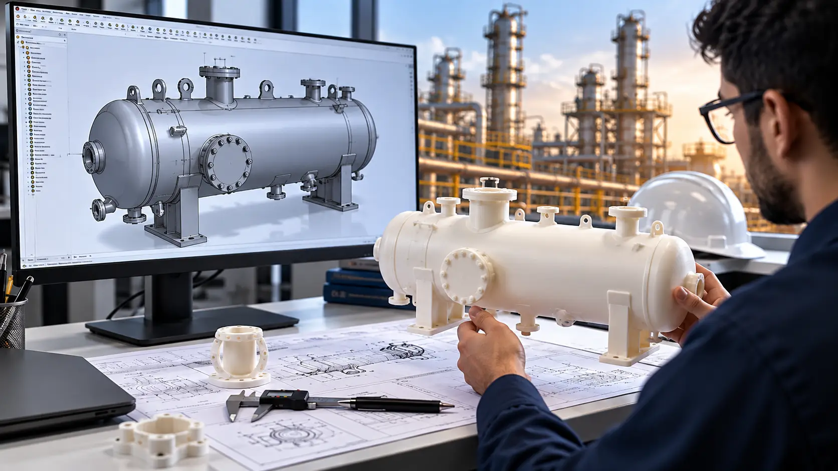
- Pressure Vessel and Process Equipment Design: Parametric relationships can help manage design variables such as vessel dimensions, component locations, support geometry, and nozzle arrangements as part of a structured engineering workflow.
When Should a Company Consider Parametric Modeling and CAD Automation?
A company may benefit from improving its parametric CAD workflow when engineers repeatedly perform tasks such as:
- Creating similar products with different dimensions.
- Updating the same set of design parameters for every project.
- Copying and modifying existing SolidWorks files.
- Manually updating drawings after design changes.
- Generating multiple product variants.
- Repeatedly exporting manufacturing files.
- Updating custom properties and BOM information manually.
- Performing repetitive CAD operations for every customer order.
The first step is often to create a structured parametric model.
The next step is to identify repetitive tasks that can be standardized or automated.
How Immersiv Techsphere Helps Manufacturers Automate SolidWorks Workflows
Immersiv Techsphere develops custom engineering automation solutions to help manufacturers reduce repetitive CAD work and improve the efficiency of engineering workflows.
Depending on the business requirement, automation solutions can be developed for workflows involving:
- SolidWorks API automation
- Parametric model automation
- Automated part and assembly generation
- Engineering drawing automation
- Product configuration workflows
- BOM automation
- DXF and CNC data generation
- PDF and STEP export
- Custom property automation
- Integration with engineering data sources
Rather than applying a one-size-fits-all approach, the automation workflow can be designed around the company’s existing engineering process and repetitive design requirements.
This can help engineering teams spend less time on repetitive model updates and more time on design, validation, and engineering decisions.
Frequently Asked Questions
Parametric modeling in SolidWorks is a method of creating 3D models using dimensions, constraints, features, equations, and relationships that control the geometry of the design. When a parameter changes, related geometry can update according to the relationships defined in the model.
It reduces the need to manually modify every affected feature. By changing key dimensions or parameters, related sketches, features, patterns, and dependent geometry can update automatically.
Parametric modeling controls geometry through features, dimensions, constraints, and relationships. Direct modeling focuses on directly manipulating geometric faces and features without relying entirely on the original feature history.
Yes. Depending on the product and engineering requirements, multiple sizes can be managed using parametric dimensions, configurations, design tables, or automation tools.
Yes. Parametric models can be combined with SolidWorks API automation, custom applications, spreadsheets, databases, or product configuration systems to automate model updates and engineering output generation.
No. Parametric modeling can improve consistency and reduce repetitive manual editing, but the model logic, relationships, engineering assumptions, and final outputs still need to be properly designed and validated.
Depending on the workflow and automation requirements, outputs may include engineering drawings, BOMs, DXF files, PDF documents, STEP files, custom property data, and other manufacturing-related information.
Conclusion
Product design changes are an unavoidable part of engineering and manufacturing. The efficiency of handling those changes depends heavily on how the CAD model is structured.
Parametric modeling in SolidWorks allows engineers to create 3D models based on dimensions, constraints, equations, and design relationships. Instead of manually rebuilding geometry for every design revision, engineers can modify key parameters and allow related elements of the model to update according to the defined design intent.
For manufacturers with frequent product variations or repetitive engineering workflows, parametric modeling can provide the foundation for a more scalable design process.
When combined with SolidWorks API automation and custom engineering automation, the workflow can extend beyond model changes to include automated generation of drawings, BOMs, DXF files, PDFs, STEP files, and other engineering outputs.
If your engineering team spends significant time making repetitive design changes in SolidWorks, Immersiv Techsphere can help evaluate your workflow and develop a custom CAD automation solution around your product and engineering process.
Have a Project in Mind?
Need help with 3D animation, industrial visualization, HSE training animation, or product visualization? Tell us about your project and our team will get back to you.