

Table of Contents
Introduction
Complex industrial equipment is often difficult to explain using static drawings or a fully assembled 3D model alone. When a product contains dozens or hundreds of components, understanding how those parts fit together, where they are located, and in what sequence they are assembled or removed can require significant engineering interpretation.
Exploded view animation provides a visual way to overcome this challenge.
By progressively separating components from an assembled 3D model, an exploded view animation can show the relationship between individual parts while preserving their overall position and assembly logic. The same approach can be used to communicate assembly, disassembly, maintenance, installation, and product structure.
This is particularly useful for heavy engineering, oil & gas equipment, pressure vessels, heat exchangers, process equipment, industrial machinery, and other complex engineered products.
At Immersiv Techsphere, engineering CAD data can be transformed into technically focused 3D animations that make complex equipment easier to understand for engineering teams, customers, operators, maintenance personnel, and other stakeholders.
What Is an Exploded View Animation?
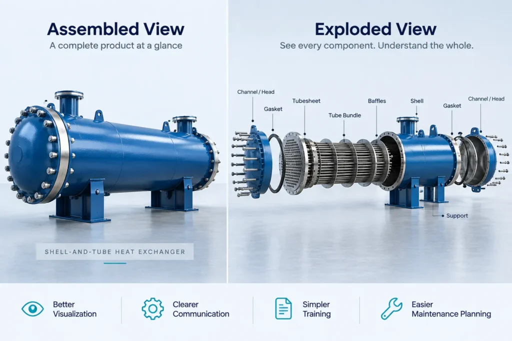
An exploded view represents an assembly with its components separated from their assembled positions so that individual parts and their relationships can be seen more clearly.
An exploded view animation takes this concept a step further by showing the components moving apart or coming back together over time.
For example, an animation of a mechanical assembly could begin with the equipment in its fully assembled condition. Components can then move outward in a controlled sequence, revealing individual parts and sub-assemblies. The animation can subsequently reverse the sequence to demonstrate how the equipment comes together.
CAD platforms such as SolidWorks support the creation and animation of exploded and collapsed assembly views. SolidWorks documentation specifically provides tools for creating exploded views and animating explode and collapse sequences.
The objective is not simply to make the equipment look visually impressive. The objective is to communicate engineering information more clearly.
Why Complex Industrial Products Are Difficult to Explain
A large industrial product may contain:
- Multiple sub-assemblies
- Fasteners and connection hardware
- Flanges and covers
- Internal components
- Structural supports
- Seals and gaskets
- Valves and instrumentation
- Tubes, tubesheets, or other heat-transfer components
- Removable service components
- Components positioned inside larger housings
When everything is shown in its final assembled state, some components may be hidden behind other parts.
A conventional 2D drawing can provide accurate technical information, but the viewer may need to interpret several views to understand the complete three-dimensional relationship.
A 3D CAD model provides another level of visualization, but a complex assembly can still become difficult to interpret when many components occupy the same space.
Exploded view animation addresses this visualization challenge by separating the components spatially and presenting their relationships sequentially.
How Exploded View Animation Improves Understanding
1. Makes Component Relationships Easier to See
One of the primary advantages of an exploded view is that components can be separated while maintaining their relationship to the overall assembly.
Instead of looking at a dense collection of overlapping components, the viewer can see:
Complete Assembly → Component Separation → Individual Parts → Assembly Relationship
This can make the structure of a complex product easier to communicate.
For example, an industrial valve assembly can be shown as a complete unit before the body, actuator, stem, seals, fasteners, and other relevant components are visually separated.
The exact components shown should depend on the equipment and the intended communication objective.
2. Explains Assembly and Disassembly Sequences
An exploded animation can communicate the order in which components are intended to be assembled or removed.
This is especially useful when a product contains multiple interdependent components.
Instead of presenting only a static exploded image, animation allows the viewer to observe the sequence:
- Identify the complete assembly.
- Separate the first component or sub-assembly.
- Continue through subsequent components.
- Reveal the internal or less visible parts.
- Reverse the sequence to demonstrate reassembly when appropriate.
SolidWorks and Autodesk both document exploded-view animation workflows for assembly and service-related visualization.
Importantly, an animation should represent the approved engineering or service procedure rather than assume that the visual sequence itself defines the correct maintenance procedure.
Large industrial equipment frequently contains components that are not visible from the outside.
Exploded views can separate external components or sub-assemblies to reveal the underlying structure.
This is valuable for equipment such as:
- Pressure vessels
- Heat exchangers
- Pumps
- Compressors
- Industrial valves
- Process equipment
- Mechanical skids
- Gearboxes
- Heavy machinery
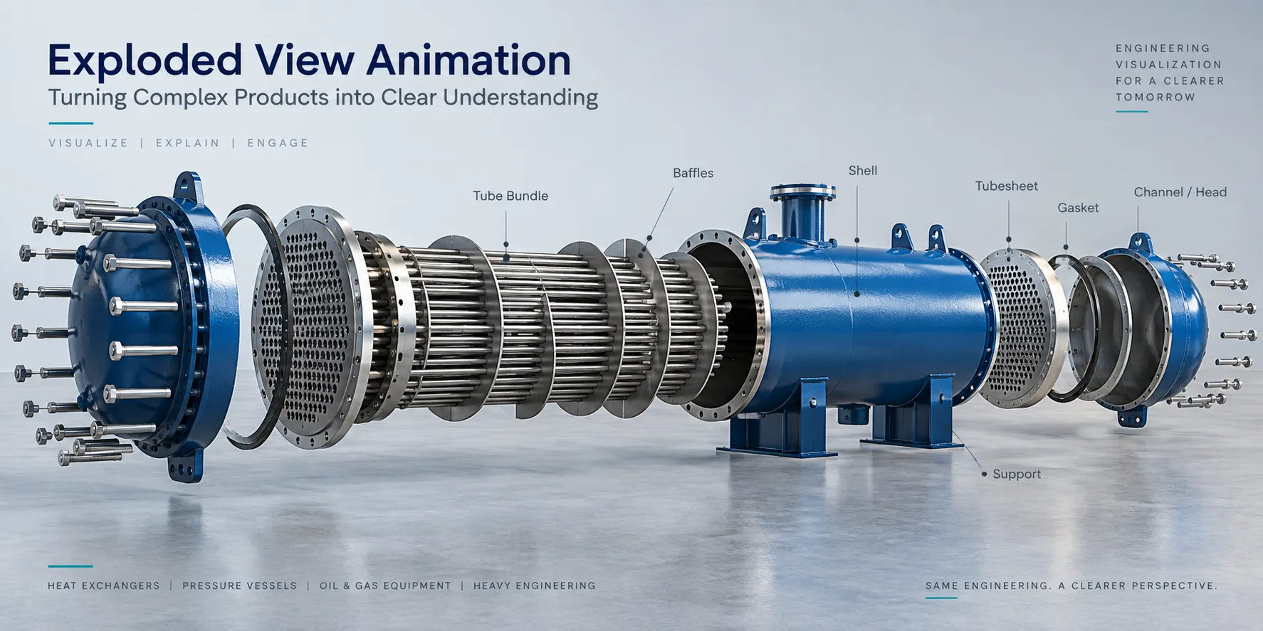
For example, an animation of a heat exchanger can visually separate external components and selected sub-assemblies to help viewers understand the relationship between the shell, channel components, tube-side elements, supports, covers, and other equipment-specific components.
The animation should be based on the actual equipment design rather than using a generic representation.
4. Reduces the Cognitive Load of Complex Drawings
Technical drawings remain essential engineering documents. However, understanding a complex assembly from several orthographic views requires spatial reasoning.
An exploded animation provides an additional visual layer.
Instead of asking the viewer to mentally reconstruct the assembly, the animation can show the relationship directly in three dimensions.
This makes the content useful for audiences who may not work with engineering drawings every day, including:
- Customers
- Procurement teams
- Sales teams
- Project stakeholders
- New employees
- Operators
- Maintenance personnel
- Installation teams
It does not replace engineering drawings or approved procedures. Rather, it complements them with a visual explanation.
Exploded View Animation for Heavy Engineering
Heavy engineering products are particularly suitable for exploded view animation because their assemblies can contain large numbers of components and complex interfaces.
Examples include:
- Heavy machinery
- Industrial skids
- Pressure equipment
- Process equipment
- Structural machinery
- Material handling equipment
- Large mechanical assemblies
- Manufacturing equipment
For a heavy industrial machine, an animation can begin with the complete machine and progressively separate major sub-assemblies.
The sequence can help viewers understand the overall product architecture before focusing on individual components.
This can be especially useful during design reviews, customer presentations, assembly documentation, training, and technical communication.
Exploded View Animation for Oil & Gas Equipment
Oil & gas equipment often combines mechanical, process, structural, and instrumentation elements in a relatively compact arrangement.
Exploded visualization can help communicate the physical construction of equipment without requiring the viewer to interpret multiple views simultaneously.
Potential applications include:
- Process equipment
- Valves and actuators
- Pump assemblies
- Compressor-related equipment
- Skid-mounted systems
- Separators
- Pressure equipment
- Piping assemblies
- Equipment packages
- Maintenance-related component visualization
For an oil & gas equipment manufacturer, an animation could show the complete equipment package first and then separate selected components to explain construction, interfaces, or service access.
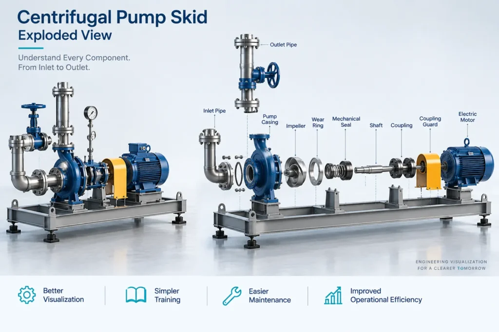
The exact sequence should always be determined from the approved engineering documentation and the intended application.
Exploded View Animation for Pressure Vessels
Pressure vessels can contain multiple external and internal components, making three-dimensional visualization valuable for technical communication.
Depending on the design, an animation may be used to visualize components such as:
- Shell sections
- Heads
- Nozzles
- Flanges
- Manways
- Internal supports
- Baffles
- Internal assemblies
- External supports
- Access components
- Connection hardware
An exploded animation can show how these components relate to the vessel as a complete assembly.
For engineering communication, it can also be combined with cutaway views, section views, component highlighting, labels, and callouts where appropriate.
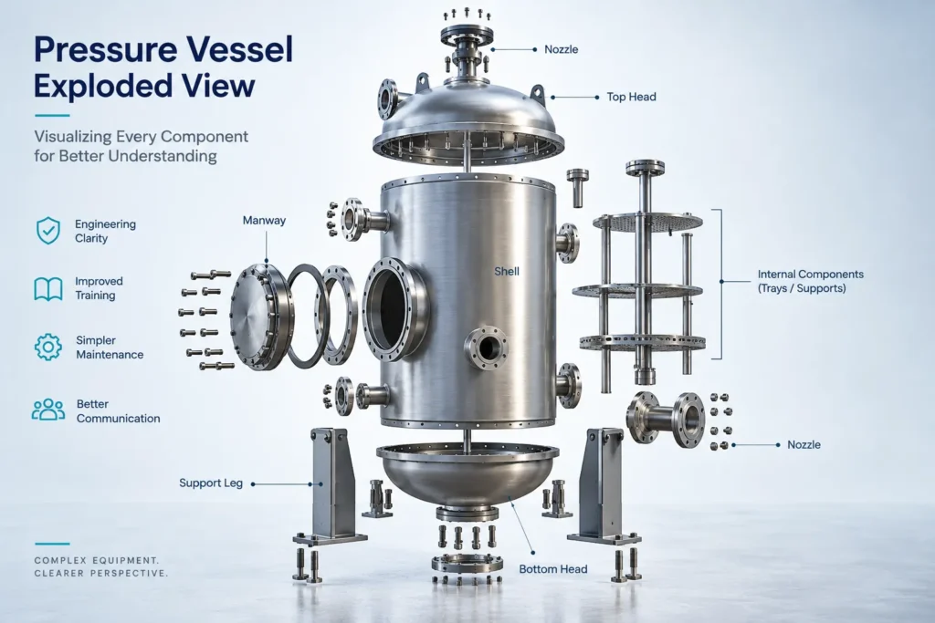
However, the animation should not be treated as a substitute for pressure-vessel design calculations, fabrication drawings, inspection documentation, or applicable codes and standards.
Its purpose is to make the existing engineering information easier to communicate.
Exploded View Animation for Heat Exchangers
Heat exchangers are another strong application because many of their important components may be hidden when the equipment is fully assembled.
For example, depending on the heat exchanger configuration, a visualization may help explain relationships between:
- Shell
- Tube bundle
- Tubesheets
- Channels
- Covers
- Baffles
- Nozzles
- Supports
- Gaskets
- Fasteners
- Other equipment-specific components
A shell-and-tube heat exchanger can be shown first as a complete unit before selected components are separated.
This can make the equipment structure easier to understand for customers, trainees, maintenance teams, and project stakeholders.
For maintenance communication, the animation can also be structured around an approved procedure to visually demonstrate component access, removal, inspection, and reassembly.
Immersiv Techsphere’s existing process equipment animation workflow similarly uses engineering CAD models and technical information to communicate equipment operation, assembly, installation, maintenance, and internal components.
From CAD Model to Exploded View Animation
A technically useful exploded animation starts with reliable engineering information.
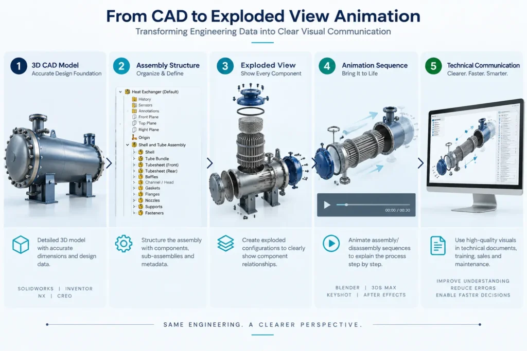
A typical workflow can include:
Step 1: Collect the Engineering Data
Depending on the project, inputs may include:
- 3D CAD assemblies
- Part models
- General arrangement drawings
- Assembly drawings
- Bills of materials
- Manufacturing drawings
- Equipment specifications
- Installation procedures
- Maintenance documentation
The available information determines what can be accurately represented.
Step 2: Understand the Assembly Structure
The assembly is reviewed to identify:
- Major components
- Sub-assemblies
- Component relationships
- Interfaces
- Fasteners
- Internal components
- Components that need to be highlighted
The goal is to determine what the viewer actually needs to understand.
Step 3: Define the Exploded Sequence
The components are organized into logical stages.
Not every component needs to move independently.
Where appropriate, related components can be grouped so that the animation remains clear and does not become unnecessarily complicated.
Step 4: Create the Exploded View
The selected components are separated from the assembled position while maintaining a meaningful spatial relationship.
In SolidWorks, exploded views can be created within an assembly configuration and subsequently animated for explode or collapse sequences.
Step 5: Add Animation and Camera Movement
The exploded sequence is converted into an animation.
Camera movement can be used to maintain focus on important components while the assembly separates.
Additional elements may include:
- Component highlighting
- Labels
- Callouts
- Section views
- Cutaways
- Transparency
- Numbered steps
- BOM references
These elements should support the engineering explanation rather than distract from it.
Step 6: Technical Review
The completed animation should be reviewed against the available engineering information.
For technical applications, the review should verify:
- Component identity
- Component positioning
- Assembly relationships
- Sequence logic
- Equipment configuration
- Labels and callouts
- Relevant installation or maintenance information
This step is particularly important when the animation is intended for installation, maintenance, training, or service communication.
Exploded View Animation vs. Static Exploded View
A static exploded view can be highly effective when the viewer needs to inspect the complete component layout at once.
An animation adds another dimension: time.
| Static Exploded View | Exploded View Animation |
|---|---|
| Shows separated components | Shows components separating over time |
| Useful in manuals and drawings | Useful for visual demonstrations |
| Viewer interprets the sequence | Sequence can be shown directly |
| Easy to include in documents | Useful for presentations and training |
| Good for reference | Good for explaining process and relationships |
The two approaches do not need to compete.
In many technical communication workflows, a static exploded illustration and an animation can complement each other.
SolidWorks Composer, for example, is designed to create technical illustrations, exploded views, assembly instructions, animations, and other technical communication outputs from CAD data.
Where Can Exploded View Animations Be Used?
Exploded view animation can support several stages of the product lifecycle.
- Engineering and Design Reviews: Use animations to communicate the structure of a complex assembly during internal or customer design reviews.
- Manufacturing and Assembly: Visualize how components relate to each other and support assembly documentation.
- Installation Planning: Show major components and their intended sequence where the sequence is defined by approved engineering or installation information.
- Maintenance Training: Visualize component access, removal, inspection, and reassembly based on approved maintenance procedures.
- Technical Sales: Help customers understand complex equipment without requiring them to interpret every detail in a technical drawing.
- Operator and Employee Training: Use animation as a visual supplement to formal training material and documented procedures.
- Product Documentation: Exploded views can be incorporated into manuals, service documentation, presentations, and other technical communication materials.
How Exploded View Animation Improves Technical Communication
The real value of an exploded animation is not the animation itself.
It is the information it communicates.
A well-planned animation can answer questions such as:
- What components make up this equipment?
- Where is a particular component located?
- How do the major sub-assemblies relate to each other?
- Which components are internal?
- What does the assembly look like when separated?
- What is the relationship between two components?
- What does the equipment look like before and after assembly?
- Which components need to be considered during a service procedure?
This makes exploded view animation particularly valuable when conventional documentation is technically accurate but difficult to interpret visually.
Why Engineering Accuracy Matters
An exploded animation is only useful when the underlying model and sequence are reliable.
A visually impressive animation can still create confusion if:
- Components are incorrectly represented.
- Parts are shown in the wrong configuration.
- Interfaces are inaccurate.
- The sequence does not correspond to the actual procedure.
- Labels identify the wrong components.
- Generic components are used instead of project-specific equipment.
For industrial applications, engineering accuracy should take priority over visual effects.
This is why CAD-based workflows are particularly useful. Existing engineering models can provide the geometric foundation for visualization, while technical documentation and stakeholder review help establish what the animation should communicate.
Immersiv Techsphere follows an engineering-focused visualization approach in which CAD models and technical information can be transformed into industrial animations for equipment communication, training, installation, and maintenance applications.
The Role of Exploded View Animation in Modern Engineering Communication
Engineering organizations increasingly have to communicate the same product to different audiences.
An engineer may need dimensional and component-level information.
A manufacturing team may need assembly information.
A maintenance team may need service access information.
A customer may simply need to understand what the equipment contains and how the major components relate to each other.
One 3D engineering model can become the foundation for multiple forms of technical communication.
This makes exploded view animation a useful part of a broader CAD-to-visualization workflow.
Instead of treating the CAD model as the final engineering output, organizations can use it as the foundation for additional technical assets such as:
- Exploded views
- Assembly animations
- Installation animations
- Maintenance animations
- Product renders
- Technical illustrations
- Training videos
- Process equipment animations
- Interactive product visualization
How Immersiv Techsphere Can Help
Immersiv Techsphere works with engineering and manufacturing data to create 3D modeling, industrial animation, product visualization, and technical communication content.
For complex industrial products, the workflow can start with existing CAD models and engineering documentation and transform them into visual content designed around a specific communication objective.
Applications can include:
- Heavy engineering equipment
- Oil & gas equipment
- Pressure vessels
- Heat exchangers
- Process equipment
- Industrial machinery
- Manufacturing equipment
- Mechanical assemblies
- Installation sequences
- Maintenance procedures
The focus is on creating visuals that make complex engineering information easier to understand while maintaining consistency with the supplied technical data.
FAQs
An exploded view animation is a 3D visualization that separates the components of an assembled product or equipment and shows their spatial relationships. It helps viewers understand how individual components relate to the complete assembly.
By separating components that may be hidden or difficult to distinguish in an assembled view, an exploded view animation allows viewers to see individual parts, sub-assemblies, and their relationships more clearly. The animated sequence can also show how components move relative to the assembly.
Yes. Exploded view animation can visualize oil & gas equipment such as process skids, pumps, valves, pressure equipment, and other mechanical assemblies. It can help communicate equipment structure and component relationships.
A pressure vessel can be visually separated into relevant components such as the shell, heads, nozzles, manways, supports, flanges, and selected internal components. This provides a clearer visual representation of the vessel’s construction and component relationships.
Yes. A shell-and-tube heat exchanger can be shown with relevant components such as the shell, tube bundle, tubesheets, baffles, channel components, covers, flanges, gaskets, and supports separated to illustrate their relationships.
Yes. Existing 3D CAD assemblies can provide the geometric foundation for an exploded view animation. The animation can then be developed from the assembly structure and relevant engineering information.
Yes. It can visually support assembly, disassembly, installation, and maintenance training by showing component locations and relationships. For procedural applications, the sequence should be based on the applicable engineering or approved procedure.
No. Exploded view animation is a visual communication tool. It complements engineering drawings, CAD models, specifications, calculations, BOMs, and approved installation or maintenance documentation rather than replacing them.
Conclusion
Exploded view animation makes complex products easier to understand by turning a static assembly into a visual sequence.
For heavy engineering, oil & gas equipment, pressure vessels, heat exchangers, and other industrial products, it can reveal component relationships that are difficult to understand from a fully assembled model or static drawing alone.
When developed from reliable CAD data and reviewed against appropriate engineering documentation, an exploded view animation can support:
- Engineering communication
- Assembly understanding
- Installation planning
- Maintenance training
- Technical sales
- Product documentation
- Customer presentations
The strongest results come from treating animation as an engineering communication tool rather than simply a visual effect.
For complex industrial equipment, the question is not only “What does the product look like?”
It is also:
“How is it structured, how do its components relate, and how can that information be communicated clearly?”
That is where exploded view animation becomes valuable.
Have a Project in Mind?
Need help with 3D animation, industrial visualization, HSE training animation, or product visualization? Tell us about your project and our team will get back to you.