

Table of Contents
Introduction
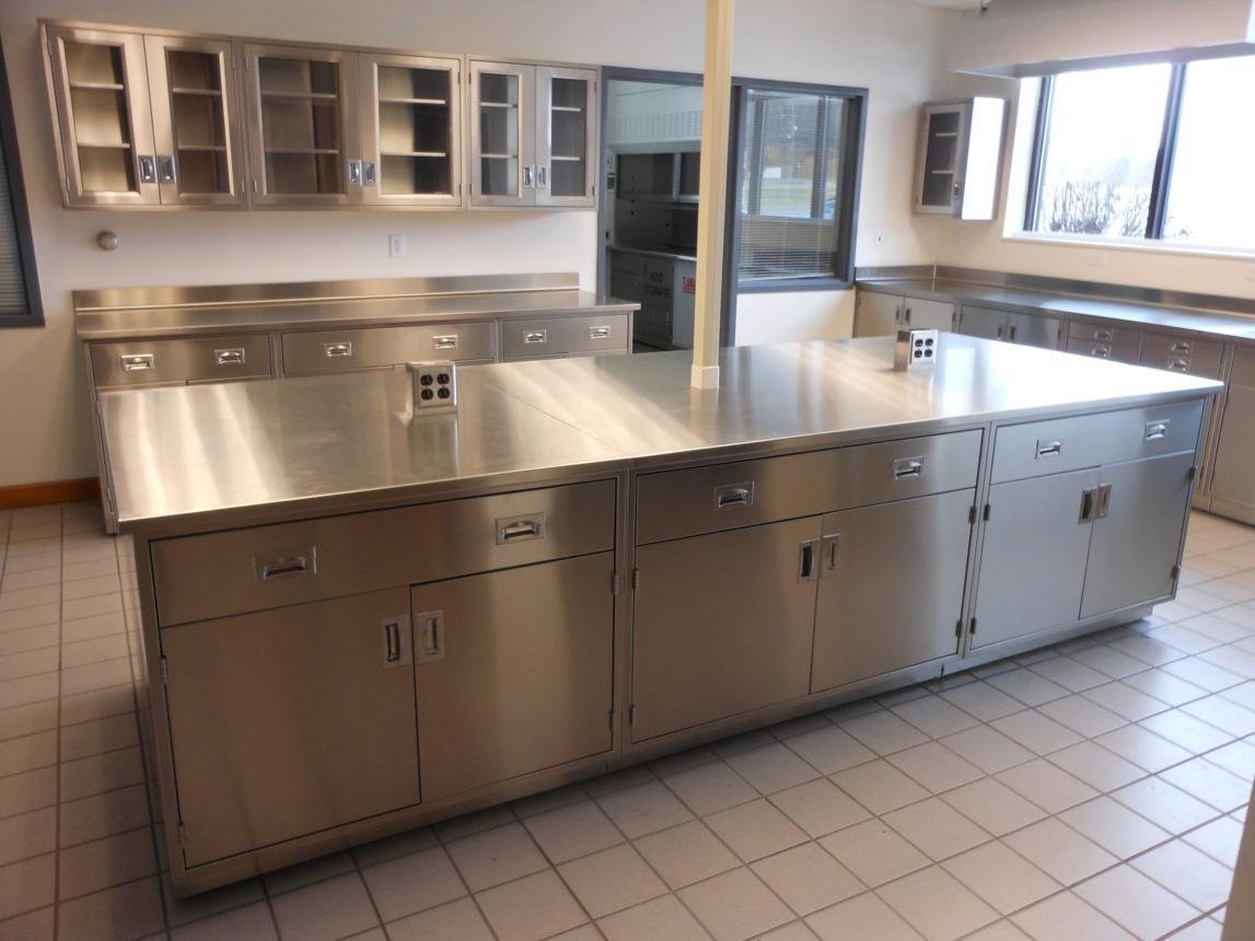
A high-quality laboratory cabinet is more than a collection of metal panels assembled together. Behind every finished cabinet or laboratory workbench is a sequence of engineering decisions, manufacturing operations, and quality checks that determine its strength, dimensional accuracy, functionality, and appearance.
From selecting the appropriate sheet material to developing a three-dimensional model and preparing manufacturing drawings, every stage contributes to the final product. Understanding this process helps laboratory furniture manufacturers, engineering teams, and project stakeholders make informed decisions before production begins.
In laboratory environments, where furniture must accommodate equipment, storage requirements, plumbing, electrical services, and demanding working conditions, the relationship between engineering design and fabrication becomes especially important.
The sheet metal fabrication process transforms flat metal sheets into finished components through a series of engineering and manufacturing operations. For laboratory cabinets and workbenches, this process typically includes material selection, 3D modelling, flat pattern development, laser cutting or CNC punching, deburring, CNC bending, welding or fastening, surface finishing, and quality inspection. Each stage plays an important role in achieving the required dimensions, structural integrity, component fit, and surface quality. Accurate 3D models and manufacturing drawings help coordinate these operations, reduce fabrication uncertainties, and ensure that the finished cabinet meets the intended design and functional requirements.
This article explores the journey from a flat sheet of metal to a finished laboratory cabinet, highlighting the manufacturing stages and explaining how accurate 3D models and manufacturing drawings support a reliable production workflow.
1. Understanding the Sheet Metal Fabrication Process
Sheet metal fabrication is a manufacturing process that transforms flat metal sheets into functional components through cutting, bending, forming, joining, and finishing.
In laboratory furniture applications, these operations are used to produce cabinet bodies, doors, drawers, shelves, workbench supports, service panels, brackets, and other structural components.
Although individual components may appear simple, assembling them into a complete cabinet requires careful coordination of dimensions, bend locations, mounting provisions, and component interfaces.
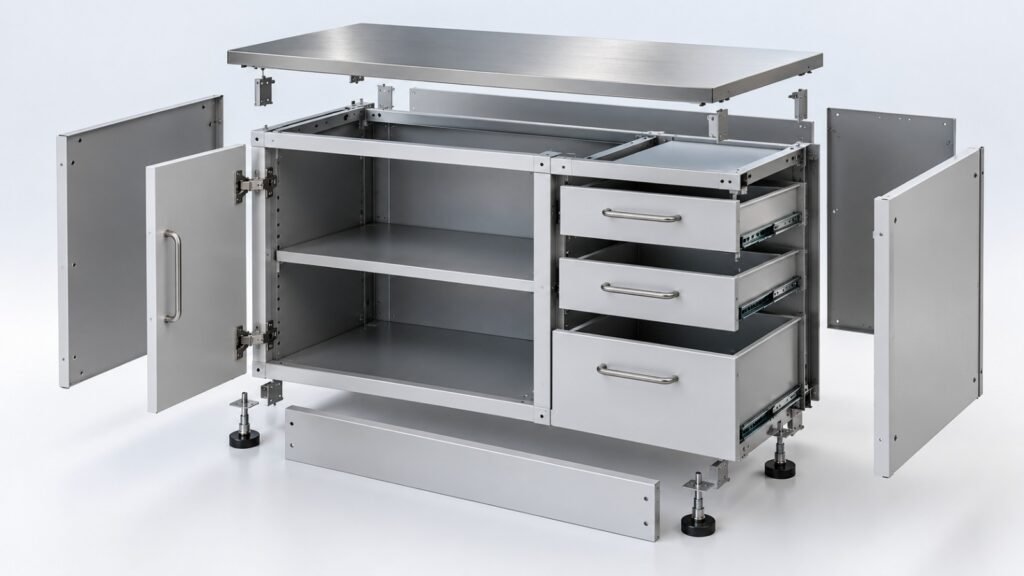
For example, a laboratory base cabinet may consist of a bottom panel, side panels, a back panel, reinforcing members, adjustable legs, doors, hinges, and hardware. Each component must be designed to fit correctly with the others. A typical manufacturing workflow follows these stages:
- Design review and engineering planning
- Material selection and flat pattern development
- Laser cutting or CNC punching
- Deburring and edge preparation
- CNC bending and forming
- Welding, fastening, and assembly
- Surface finishing
- Final inspection and quality verification
The precise sequence depends on the cabinet design, material, production method, and required finish. However, the objective remains the same: to transform engineering information into a functional, accurately manufactured product.
2. Material Selection: The Foundation of Cabinet Design
Material selection is one of the first considerations in laboratory furniture engineering. The selected material affects structural performance, corrosion resistance, weight, appearance, fabrication requirements, and overall project cost.
Common materials used in sheet metal applications include mild steel, galvanized steel, and stainless steel. The appropriate choice depends on the laboratory environment and the intended use of the furniture:
- Mild Steel: Mild steel is commonly used for cabinet structures, workbench supports, brackets, and other components where strength, fabrication flexibility, and cost are important considerations. A suitable protective coating is generally required when corrosion resistance is needed.
- Stainless Steel: Stainless steel is selected for applications requiring corrosion resistance, cleanability, and a durable surface. The appropriate grade depends on exposure conditions, cleaning chemicals, and the intended laboratory application.
- Galvanized Steel: Galvanized steel has a protective zinc coating that helps resist corrosion. Its suitability depends on the fabrication sequence, exposed edges, joining method, and required final finish.
Material selection should also consider sheet thickness, bend radius, surface grain direction, and the manufacturing processes that will be used.
For laboratory cabinets and workbenches, the material specification should be established early in the design process. Changing material or thickness after engineering is complete can affect part dimensions, bending behavior, component weight, and manufacturing documentation.
3. Converting the Design into a 3D Model
Before fabrication begins, the intended product must be translated into a clear and coordinated engineering model.
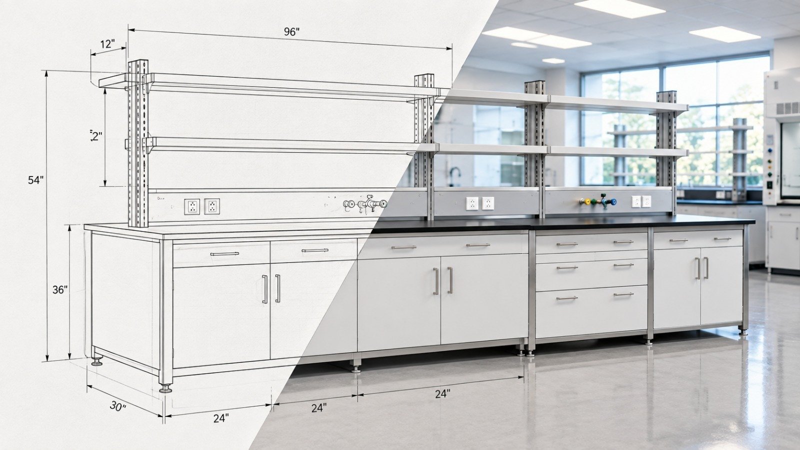
A 3D model allows designers and manufacturing teams to understand the cabinet’s overall geometry, component relationships, clearances, and assembly arrangement before physical production.
For a typical laboratory cabinet, the model may include the cabinet body, doors, drawers, shelves, hinges, handles, leveling feet, mounting brackets, and other hardware.
For laboratory workbenches, the model may also incorporate support frames, countertop interfaces, service fixtures, shelving, and equipment mounting provisions.
Why 3D Modeling Matters
A properly developed 3D model helps engineering teams:
- Verify overall dimensions and component positioning.
- Identify interference between doors, drawers, panels, and hardware.
- Check clearances for installation and maintenance.
- Coordinate interfaces between cabinets, countertops, and support structures.
- Visualize the final assembly before manufacturing.
- Communicate design intent more clearly to clients and production teams.
Consider a cabinet with a door-mounted handle and an adjacent drawer. Reviewing the assembly in 3D can help identify clearance issues that may not be immediately obvious in an individual component drawing.
However, a 3D model alone does not communicate every manufacturing requirement. It must be supported by appropriate drawings, dimensions, material specifications, and fabrication details.
4. Manufacturing Drawings: Turning Geometry into Production Information
Manufacturing drawings bridge the gap between the digital design and the fabrication floor.
While a 3D model communicates the product’s shape and assembly, manufacturing drawings provide the dimensions, specifications, and instructions required to manufacture and inspect individual components.
Depending on the project, a drawing package may include:
- General arrangement drawings
- Assembly drawings
- Individual sheet metal part drawings
- Flat pattern drawings
- Bend dimensions and bend notes
- Material and thickness specifications
- Hole, slot, and cutout dimensions
- Welding and fastening details
- Surface finish requirements
- Bill of materials and hardware information
For sheet metal components, accurate flat patterns are particularly important. The flat pattern must account for the material and the bending process so that the formed component achieves the intended dimensions.
Bend allowance, bend deduction, inside bend radius, tooling, and material behavior all influence the relationship between the flat blank and the finished part.
For this reason, flat patterns should be developed using suitable material and fabrication settings and verified against the manufacturing process.
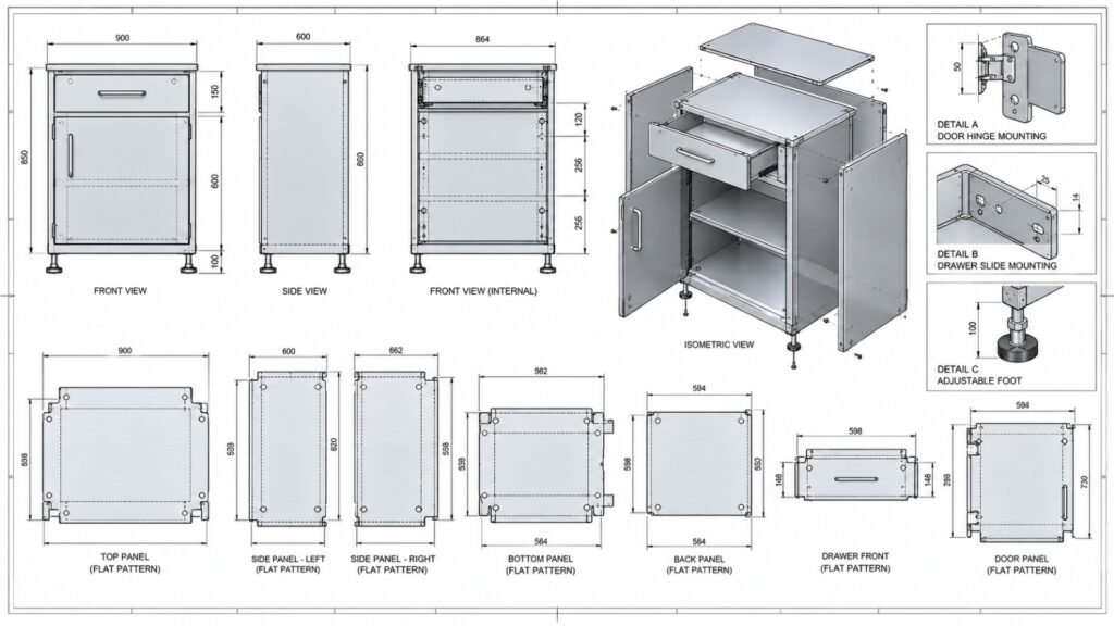
A missing dimension, unclear bend direction, or incorrect hardware specification can create uncertainty during production. Complete and coordinated drawings reduce the need for assumptions and help keep engineering and manufacturing teams aligned.
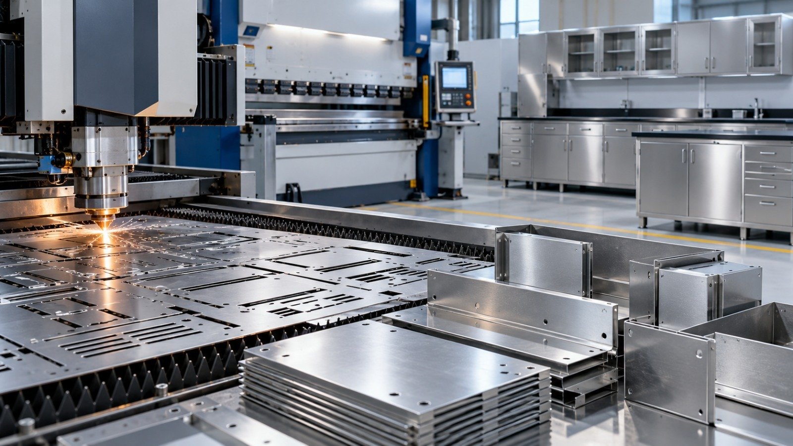
5. Laser Cutting and CNC Punching
Once the flat pattern is finalized, the sheet metal blank can be cut to the required shape.
Laser cutting is widely used for producing accurate profiles, openings, slots, and complex contours. CNC punching can also be suitable for components with repeated holes, standard forms, and particular production requirements.
In laboratory furniture, these processes may be used to produce:
- Cabinet side and back panels
- Door and drawer fronts
- Ventilation openings
- Mounting brackets
- Service access cutouts
- Shelving components
- Workbench support plates
The quality of this stage affects subsequent bending and assembly. Incorrect hole locations, missing cutouts, or unsuitable edge conditions may create problems later in the production process.
Nesting is another important consideration. Arranging parts efficiently on a sheet can improve material utilization and reduce avoidable waste, provided the required part orientation and finish direction are maintained.
Engineering data must also be coordinated with the manufacturing process to ensure that the correct drawing revision and geometry are used.
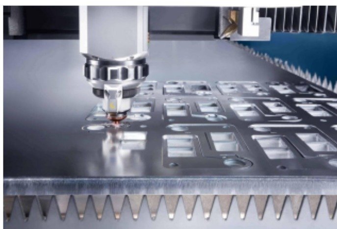
Laser Cutting vs. CNC Punching: Which Process Is Suitable for Laboratory Cabinets?
Laser cutting and CNC punching are both widely used in sheet metal fabrication. The appropriate method depends on component geometry, hole patterns, tooling requirements, production volume, material specifications, and the required edge quality.
| Comparison Factor | Laser Cutting | CNC Punching |
|---|---|---|
| Component geometry | Suitable for complex profiles, intricate contours, slots, and custom cutouts | Suitable for components with repeated holes, standard shapes, and features supported by available tooling |
| Tooling requirements | Does not require dedicated punch tooling for each profile, although machine setup and process parameters are still necessary | Requires suitable punch and die tooling for the required features |
| Hole and cutout patterns | Flexible for varied hole sizes, irregular openings, and frequently changing designs | Efficient for repeated holes and standard forms when suitable tooling is available |
| Design changes | Generally accommodates profile changes without replacing dedicated cutting tools | Changes may require different tooling or adjustments to the punching program |
| Production requirements | Useful for prototypes, custom components, and varied part geometries | Can be advantageous for repetitive production involving standard features and compatible tooling |
| Edge and feature considerations | Quality depends on material, thickness, cutting parameters, and machine capability | Feature quality depends on tooling condition, clearances, material, and punching parameters |
| Typical laboratory furniture applications | Custom cabinet panels, ventilation openings, intricate cutouts, and specialised mounting profiles | Repeated mounting holes, standard perforations, and components with recurring punched features |
How to Choose the Right Process
For laboratory cabinet manufacturing, laser cutting is often suitable when design flexibility and complex profiles are important, particularly for custom panels and components with varied cutouts. CNC punching can be a practical option for repeated hole patterns and standard features when the required tooling is available.
The two processes can also be used within the same manufacturing workflow. For example, a cabinet manufacturer may use laser cutting for complex panel outlines and CNC punching for components containing recurring standard holes.
The final selection should consider the material and sheet thickness, component geometry, required tolerances, tooling availability, production volume, machine capacity, and overall manufacturing cost. Evaluating these factors during engineering planning helps align the selected process with the cabinet design and production requirements.
6. CNC Bending: Creating Three-Dimensional Components
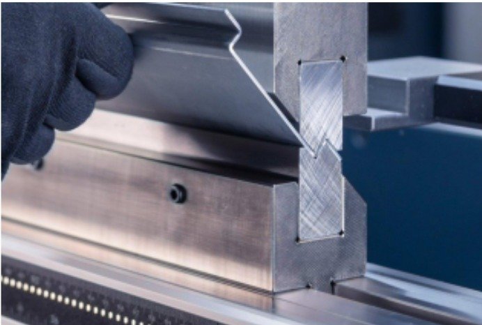
After cutting, the flat sheet is formed into the required geometry using a press brake or another suitable forming method.
Bending transforms flat blanks into channels, trays, flanges, cabinet bodies, door returns, and other structural features.
Although the operation may appear straightforward, achieving consistent dimensions requires attention to several factors:
- Material thickness and properties
- Inside bend radius
- Bend angle and springback
- Flange dimensions
- Bend sequence
- Tooling limitations
- Hole and cutout proximity to bends
The bend sequence must also be practical. A component may be geometrically correct in a 3D model but difficult to manufacture if a later bend is blocked by an already formed flange.
For laboratory cabinets, bending accuracy is especially important where multiple panels must fit together or where door alignment depends on the dimensions of the cabinet body.
Well-prepared manufacturing drawings help operators understand the intended geometry and identify the dimensions that must be controlled.
7. Welding, Fastening, and Cabinet Assembly
Once individual components have been cut and formed, they can be joined using suitable welding methods, mechanical fasteners, or other joining techniques.
The appropriate method depends on the design, material, structural requirements, appearance, accessibility, and manufacturing process.
For example, cabinet bodies may incorporate welded joints, while doors, hinges, handles, shelves, and replaceable components may use mechanical fasteners.
Assembly introduces additional considerations beyond the accuracy of individual parts. Even when every component meets its specified dimensions, accumulated variation can affect the fit of the overall product.
Welding can also introduce heat-related distortion, particularly in thin sheet metal components. Appropriate joint design, fixtures, welding sequence, and inspection can help manage these effects.
For laboratory cabinets and workbenches, important assembly checks may include:
- Cabinet squareness and overall dimensions
- Door and drawer alignment
- Hinge and handle positioning
- Shelf and bracket fit
- Countertop and adjacent cabinet interfaces
- Stability and support arrangements
These checks help ensure that the fabricated product performs as intended rather than merely matching its individual component drawings.
8. Surface Finishing and Appearance
Surface finishing influences the appearance, durability, and suitability of laboratory furniture.
Depending on the material and application, finishing processes may include powder coating, painting, brushing, polishing, or other specified surface treatments.
The selected finish should be considered during engineering because it can affect appearance, surface protection, masking requirements, and certain dimensional interfaces.
For example, a powder-coated cabinet may require attention to mating surfaces, threaded holes, grounding provisions, and areas where coating buildup could affect assembly.
Visible surfaces also require careful handling throughout fabrication. Scratches, inconsistent grain direction, weld marks, and uneven coating can affect the appearance of the completed product.
A consistent finishing specification helps maintain a uniform appearance across multiple cabinets and workbench components.
For laboratory furniture, the final finish should be selected according to the intended environment, cleaning requirements, chemical exposure, and client specifications rather than appearance alone.
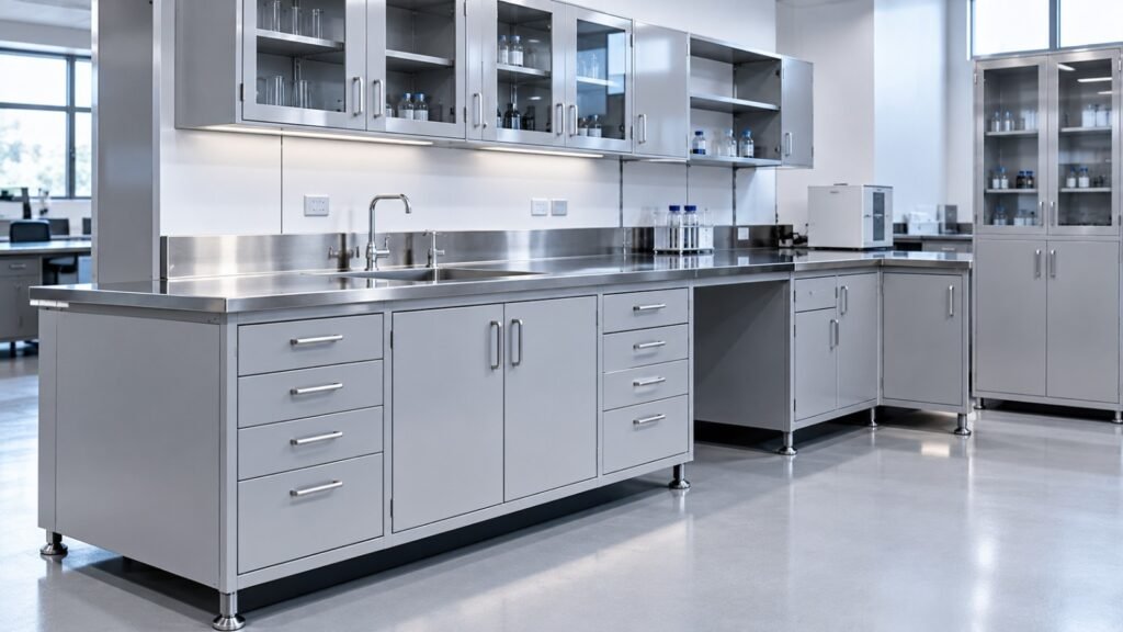
9. Quality Inspection: Verifying the Finished Product
Quality inspection should not be limited to the final stage. Verification at key points throughout manufacturing can identify problems before they affect subsequent operations.
For example, checking a flat blank before bending may reveal an incorrect cutout, while inspecting a formed panel can help identify a dimensional issue before welding or assembly.
A practical inspection plan may include:
- Dimensional inspection: Verifying critical dimensions, hole positions, flange lengths, and overall geometry.
- Forming inspection: Checking bend angles, radii, flange dimensions, and component shape.
- Assembly inspection: Confirming alignment, fit, clearances, and hardware installation.
- Surface inspection: Reviewing coating consistency, visible scratches, sharp edges, and finish quality.
- Documentation review: Confirming that the manufactured product corresponds to the approved drawings and specifications.
Inspection requirements should reflect the project’s functional needs. Critical dimensions and interfaces should be clearly identified in the engineering documentation so that manufacturing and inspection teams understand what must be verified.
10. How Engineering Documentation Supports Manufacturing Success
The manufacturing process is only as reliable as the information used to execute it.
A detailed 3D model, coordinated manufacturing drawings, and clearly defined specifications help connect the design stage with fabrication, assembly, and inspection.
When these deliverables are incomplete or inconsistent, production teams may need to interpret missing information, request clarifications, or make assumptions. Such situations can lead to rework, delays, material waste, and assembly difficulties.
Engineering documentation is therefore not simply a collection of drawings. It is a communication system that connects design intent with manufacturing requirements.
For laboratory furniture projects involving multiple cabinet sizes, repeated components, different hardware options, or coordinated workbench layouts, maintaining consistent and accurate documentation becomes even more important.
Engineering teams can support this process by reviewing assemblies, verifying interfaces, coordinating part dimensions, preparing manufacturing drawings, and ensuring that revisions are reflected in the relevant deliverables.
This approach helps establish a clearer path from the initial design concept to the finished product.
FAQs
The main stages typically include engineering design, material selection, flat pattern development, cutting, deburring, bending, joining, surface finishing and quality inspection. The exact sequence depends on the component design and manufacturing method.
Flat patterns define the blank geometry before forming. They must account for material properties, bend allowance or deduction, bend radius and the intended fabrication process to help achieve the required finished dimensions.
3D modelling helps verify component relationships, door and drawer clearances, hardware positions, installation space and interfaces between cabinets and workbenches before fabrication begins.
Depending on the part and project, drawings may include dimensions, material grade and thickness, bend details, hole and cutout locations, tolerances, joining instructions, finish specifications and hardware information.
CAD automation can help standardise repetitive design tasks, generate drawings and flat patterns, and manage configurable cabinet variants. Its suitability depends on the product family, CAD system, manufacturing rules and required validation.
Conclusion
Transforming a flat sheet into a finished laboratory cabinet requires more than cutting and bending metal. It involves coordinated engineering, appropriate material selection, accurate 3D modelling, practical fabrication planning, careful assembly, and systematic quality inspection.
Every stage influences the final product. Material selection affects forming behaviour and durability, bend accuracy determines component fit, welding can introduce distortion, and surface finishing influences both appearance and assembly. Accurate 3D models and manufacturing drawings help coordinate these operations, communicate design intent, and identify potential fabrication issues before production begins.
For laboratory furniture manufacturers, investing in sheet metal cabinet design and engineering documentation helps reduce manufacturing uncertainty, improve coordination between design and production teams, and support consistent fabrication outcomes.
At Immersiv Techsphere, we provide 3D modelling, sheet metal cabinet design, and manufacturing drawing services for laboratory cabinets, workbenches, and configurable sheet metal furniture. Our engineering deliverables help manufacturers coordinate component geometry, flat patterns, assembly interfaces, and fabrication requirements.
Planning a laboratory furniture project?
Contact Immersiv Techsphere to discuss your sheet metal design and manufacturing drawing requirements.
Have a Project in Mind?
Need help with 3D animation, industrial visualization, HSE training animation, or product visualization? Tell us about your project and our team will get back to you.