

Table of Contents
Introduction: More Than Just a 3D Model
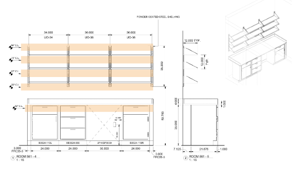
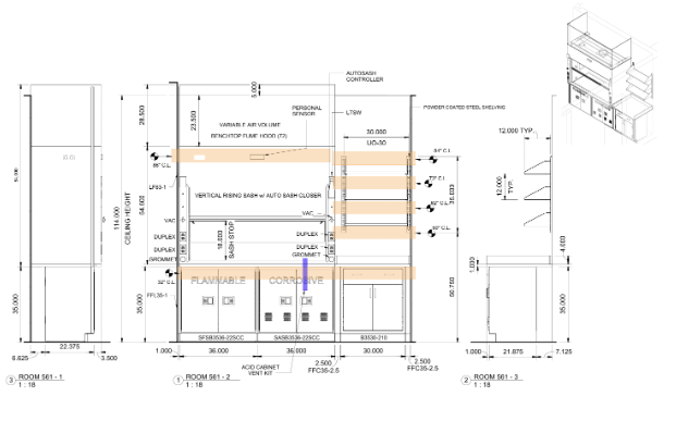
In modern laboratory projects, Revit has become an important part of the design and documentation process. Laboratory casework, workstations, cabinets, sinks, equipment supports, and other furniture components are often represented as Revit families and then incorporated into larger coordinated models. But a Revit family should be more than a 3D object that looks correct on screen.
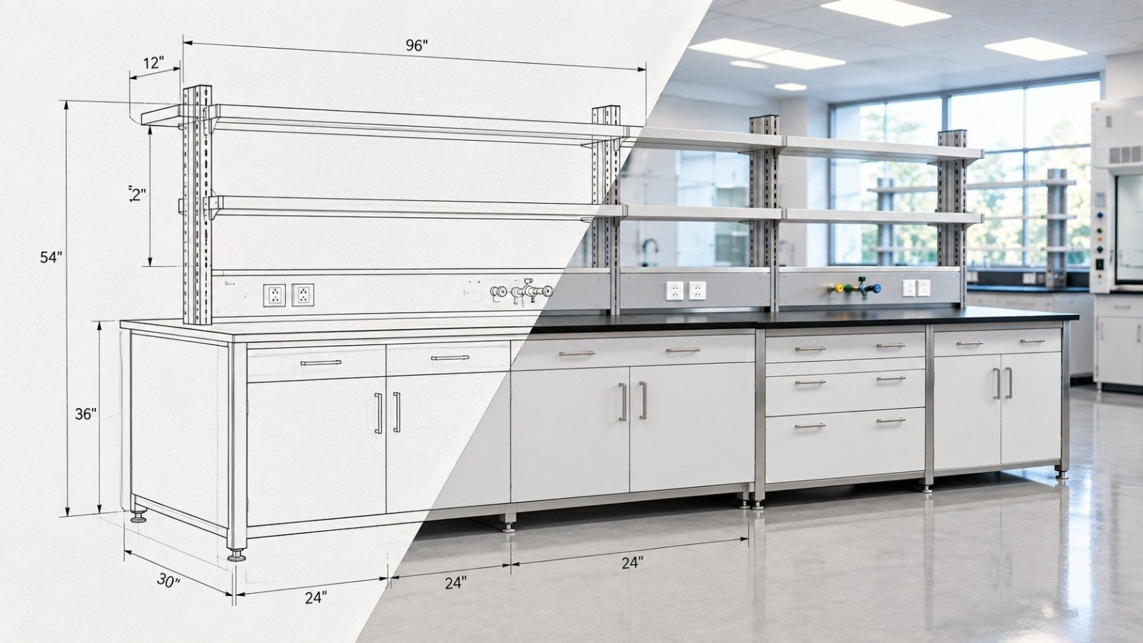
For laboratory furniture, digital accuracy matters because the model often becomes a bridge between design intent and the physical product. Dimensions, clearances, doors, drawers, shelves, hardware, service openings, countertop relationships, and construction details can all influence fabrication, installation, coordination, and ultimately how the laboratory functions.
A family that is visually convincing but physically unrealistic can create problems later in the project. Conversely, a carefully developed family that reflects the manufacturer’s product and real fabrication methods can improve coordination, documentation, and confidence throughout the project.
What Makes a Revit Laboratory Furniture Family Accurate?
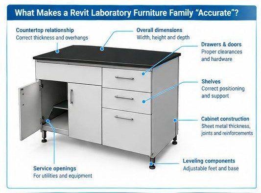
Accuracy begins with understanding what the family is intended to represent. A laboratory cabinet is not simply a box with doors. Its geometry represents a collection of physical components that must work together.
- Overall dimensions: width, height, and depth should correspond to the intended product configuration.
- Cabinet construction: panels, backs, bases, reinforcements, and sheet-metal construction should be represented appropriately for the required level of detail.
- Doors and drawers: opening sizes, clearances, hardware locations, and relationships should reflect the actual product.
- Shelves: shelf positions, support methods, and adjustability should be considered where relevant.
- Countertop relationship: cabinet height, countertop thickness, overhangs, and edge conditions must work together.
- Leveling components: feet, bases, or leveling systems should be positioned realistically.
- Service openings: plumbing, electrical, gas, or equipment access openings should be considered when they affect coordination.
- Parametric behavior: adjustable dimensions should change related components logically rather than producing impossible or disconnected geometry.
The objective is not necessarily to model every screw, weld, or hidden component. The objective is to model the information that matters for the intended use of the family.
The Connection Between Revit and Manufacturing
The most important question during family development is: “Could this digital product actually be built?” This question encourages the designer to think beyond appearance and consider manufacturing.
For sheet-metal laboratory furniture, a typical physical workflow may involve laser cutting or CNC cutting, sheet-metal bending, welding, grinding, finishing, hardware installation, assembly, and inspection. Every stage imposes practical constraints on the geometry.
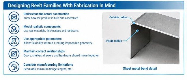
For example, a sheet-metal panel cannot simply be bent wherever a designer wants. The material thickness, tooling, inside bend radius, flange length, bend sequence, and available machine capacity can all influence the final component. If the Revit family ignores these realities, the digital model may communicate an inaccurate construction concept.
This does not mean every Revit family must become a fabrication model. Instead, the family should contain the right level of physical logic for its purpose and should not contradict the way the product is manufactured.
Common Digital Modeling Mistakes
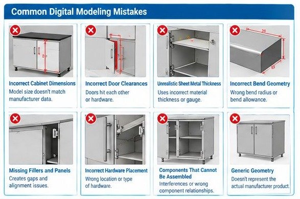
Small errors in a digital family can become larger problems when the family is placed into a project, used for documentation, or compared with manufacturer information. Some common issues include:
- Incorrect cabinet dimensions that do not match manufacturer information.
- Door clearances that are too small, too large, or inconsistent with the actual hardware.
- Unrealistic sheet-metal thickness or geometry.
- Bend geometry that cannot be produced with practical tooling or bend allowances.
- Missing fillers, panels, access spaces, or support components required for installation.
- Hardware located in positions that interfere with doors, drawers, shelves, or adjacent components.
- Nested components that move incorrectly when the main family changes size.
- Generic geometry that represents the appearance of a product but does not represent its actual construction.
- Parameters that allow combinations of dimensions that would not be manufacturable.
These issues are especially important when a family is intended for submittal drawings, schedules, quantity takeoffs, coordination, or direct comparison with a manufacturer’s product.
Designing Revit Families With Fabrication in Mind
A fabrication-aware Revit family starts with knowledge of the real product. Before modeling, designers should review available manufacturer information, including cutsheets, specifications, CAD drawings, STEP files, installation information, photographs, and other technical references.
- Understand the actual construction. Identify panels, bends, seams, reinforcements, hardware, and assembly relationships.
- Model realistic components. Use appropriate material thicknesses, component relationships, and construction logic where required.
- Use parameters carefully. Parameters should provide useful flexibility without allowing physically impossible configurations.
- Maintain component relationships. Doors, drawers, shelves, hardware, and other nested components should respond correctly when dimensions change.
- Consider manufacturing limitations. Account for bend radii, minimum flange lengths, clearances, access for welding, and assembly requirements.
- Define the intended level of detail. Model what is necessary for coordination and documentation without adding unnecessary complexity.
The result should be a family that behaves predictably when used in different project conditions. A good parametric family is flexible, but its flexibility is controlled by real-world design logic.
When these design requirements are repetitive or involve configurable product ranges, CAD automation can further standardize design outputs and reduce repetitive engineering work.
Parametric Flexibility vs. Manufacturing Accuracy
Parametric modeling is one of Revit’s biggest advantages, but flexibility must be used carefully. A cabinet family may need to support multiple widths, heights, depths, door configurations, or shelf arrangements. Changing one parameter can therefore affect many related components.
For example, if cabinet width changes, the doors should resize or reposition appropriately, shelves should maintain the intended relationship, and hardware should remain in usable locations. If cabinet height changes, the countertop, doors, shelves, and leveling components should respond logically.
A family that can technically accept a value is not necessarily a family that can physically support that value. Good parametric design therefore combines mathematical relationships with manufacturing knowledge.
Why Manufacturer References Matter
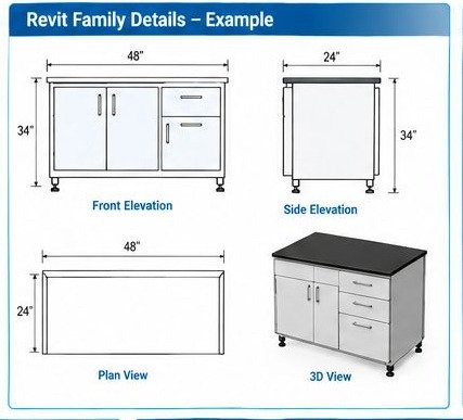
Manufacturer documentation is one of the most valuable sources of information when creating accurate laboratory furniture families. A STEP model can reveal physical geometry that may not be obvious from a simple product image. Cutsheets can provide dimensions and configurations. CAD drawings can clarify construction details, while photographs can help verify how the product appears and is assembled in the real world.
Using multiple references is particularly useful because no single document may contain all the information needed. The goal is to build a consistent understanding of the product before translating it into a Revit family.
- STEP files: useful for understanding 3D geometry and component relationships.
- Cutsheets: useful for dimensions, configurations, specifications, and product options.
- CAD drawings: useful for elevations, sections, details, and dimensional information.
- Product photographs: useful for visual verification and identifying real-world components.
- Installation information: useful for clearances, service requirements, and assembly considerations.
Quality Control Before Delivering a Revit Family
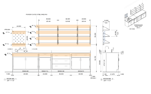
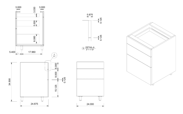
A structured quality-control process can identify problems before a family reaches the project model. A useful review can include the following checks:
- Dimension check: compare overall dimensions against approved manufacturer information.
- Geometry check: inspect doors, drawers, shelves, panels, hardware, and construction relationships.
- Parameter check: test minimum, typical, and maximum intended configurations.
- Visibility check: verify geometry at the required detail levels and view types.
- Schedule check: confirm that the family reports the intended information and quantities.
- Project placement check: place the family in a real project environment and verify clearances and coordination.
- Documentation check: compare elevations, sections, and 3D views against the intended product.
- Manufacturer comparison: perform a final visual and dimensional comparison with the available reference information.
Testing the family inside an actual project environment is particularly valuable. A family that looks correct in the Family Editor may behave differently when hosted, scheduled, tagged, or coordinated with adjacent architectural and engineering elements.
From Digital Model to Real Laboratory Furniture
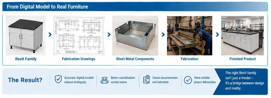
The complete workflow can be viewed as a continuous information chain:
- Real product or approved design intent
- Manufacturer information and technical references
- Accurate Revit family development
- Project model and multidisciplinary coordination
- Submittal drawings, schedules, and documentation
- Fabrication information and manufacturing
- Installation and final laboratory furniture
For sheet-metal laboratory furniture, this transition also depends on manufacturing-ready engineering information covering material thickness, bend requirements, fabrication details, and component relationships. Professional sheet metal design services can help translate these requirements into practical designs and production documentation.
The strength of this workflow comes from maintaining consistency between each stage. If the digital model changes but the supporting documentation does not, or if the Revit family represents a different configuration from the physical product, confusion can occur.
For this reason, digital accuracy is not only about making a model look right. It is about creating reliable information that can be understood and used by designers, engineers, fabricators, contractors, installers, and clients.
The Business and Project Benefits of Accurate Digital Models
Accurate Revit families can provide benefits beyond visual coordination. When the model reflects the intended product, project teams can communicate using a common digital reference.
- Reduced ambiguity during coordination.
- Clearer submittal and documentation workflows.
- More reliable schedules and quantity information.
- Better communication between design and fabrication teams.
- Earlier identification of clearance and installation conflicts.
- More consistent representation of manufacturer products.
- Improved confidence when moving from digital design to physical fabrication.
These benefits become increasingly important on projects with large quantities of laboratory casework or highly customized furniture, where small inconsistencies can multiply across many rooms and components.

How Immersiv Techsphere Supports Laboratory Furniture Design
Immersiv Techsphere supports laboratory furniture manufacturers with services that connect digital models with approval and manufacturing requirements. Our services include Revit family development for accurate and parametric laboratory furniture, 3D laboratory furniture design for cabinets, workbenches, and storage units, client approval drawings for design review, manufacturing and DFM drawings aligned with fabrication requirements, fabrication drawings and BOMs for production, SKU building and cataloguing for standard and configurable products, custom laboratory furniture design for project-specific requirements, and SEFA-compliant design support considering applicable standards, manufacturability, durability, and ergonomics.
FAQs
It should accurately represent dimensions, construction, materials, hardware, service openings, and other fabrication-critical details.
Information such as material thickness, bend radius, tooling, flange lengths, and machine limitations helps create fabrication-aware families.
STEP files, CAD drawings, cutsheets, photos, and installation data help ensure the digital model accurately represents the physical product.
Parameters should allow required design variations while maintaining component relationships and restricting configurations that cannot be physically produced.
Validation should cover dimensions, geometry, parameters, visibility, schedules, project placement, documentation, and comparison with manufacturer data.
Conclusion: Building the Bridge Between Digital and Physical
A Revit family is most valuable when it represents more than appearance. It should communicate the important characteristics of the real product: its dimensions, components, relationships, configurations, and intended use.
For laboratory furniture, this means connecting digital modeling with manufacturer information, engineering judgment, fabrication knowledge, and project coordination. When these elements are considered together, Revit becomes more than a visualization tool—it becomes an important link between design intent and the physical laboratory.
The right Revit family is therefore not simply a model of a cabinet. It is a digital representation that helps teams understand, coordinate, document, and ultimately deliver the real product.
Have a Project in Mind?
Need help with 3D animation, industrial visualization, HSE training animation, or product visualization? Tell us about your project and our team will get back to you.