

Table of Contents
Introduction
Manufacturing costs are often associated with raw materials, labor, machining, or assembly. However, one of the biggest factors influencing production cost is determined much earlier, during the product design stage.
Studies across the manufacturing industry consistently show that engineering decisions made during product development influence the majority of a product’s total manufacturing cost. A design that appears functional in a CAD model may require unnecessary machining operations, complex tooling, excessive welding, or difficult assembly processes, all of which increase production time and expenses.
This is where Design for Manufacturing (DFM) becomes essential.
Rather than focusing solely on product functionality, DFM ensures that every design decision considers how efficiently and economically the product can be manufactured. From selecting appropriate materials to simplifying part geometry and standardizing components, DFM helps manufacturers reduce costs without compromising quality or performance.
Whether you’re developing industrial equipment, sheet metal enclosures, laboratory furniture, fabricated structures, or custom machinery, integrating DFM early in the design process leads to faster production, improved product consistency, and fewer manufacturing issues.
In this guide, we’ll explore the principles of Design for Manufacturing, explain how better engineering decisions reduce manufacturing costs, discuss practical DFM strategies across different manufacturing processes, and share examples of how optimized designs improve production efficiency.
What is Design for Manufacturing (DFM)?
Design for Manufacturing (DFM) is an engineering methodology that focuses on designing products so they can be manufactured as efficiently, reliably, and cost-effectively as possible.
Instead of optimizing only for appearance or functionality, DFM considers every stage of manufacturing, including:
- Material selection
- Fabrication methods
- Machining operations
- Sheet metal processing
- Welding
- Assembly
- Surface finishing
- Inspection
- Packaging
The objective is straightforward:
Create products that are easier, faster, and less expensive to manufacture while maintaining the required quality and performance.
A well-executed DFM process minimizes unnecessary manufacturing complexity, reduces production errors, and shortens lead times.
DFM in Simple Terms
Imagine designing two sheet metal cabinets.
- The first design includes:
- Multiple custom brackets
- Tight machining tolerances on every hole
- Twelve different fastener sizes
- Complex welded joints
- Difficult assembly access
- The second design performs the same function but features:
- Standard hardware
- Fewer fabricated parts
- Simplified bends
- Optimized weld locations
- Accessible fastening points
- Standard hole sizes
Both products deliver the same functionality.
However, the second design can typically be manufactured more quickly, assembled with fewer errors, inspected more easily, and maintained at a lower overall cost. That is the practical value of Design for Manufacturing.
Why DFM Matters More Than Ever
Modern manufacturing environments face increasing pressure to:
- Reduce production costs
- Shorten product development cycles
- Improve product quality
- Respond quickly to customer demands
- Minimize waste
- Handle supply chain uncertainties
Without DFM, engineering teams often release designs that appear technically correct but introduce avoidable manufacturing challenges, such as:
- Excessive machining time
- High material waste
- Difficult welding operations
- Complex assembly sequences
- Expensive tooling requirements
- Increased quality inspection effort
- Higher scrap rates
- Frequent engineering change requests (ECRs)
By evaluating manufacturability during the design phase, organizations can address these issues before production begins.
Why Manufacturing Cost Begins During the Design Phase
Many organizations assume manufacturing costs are primarily determined on the shop floor. In reality, engineering decisions made during product development have a far greater impact.
Every design choice influences production expenses, including:
1. Material Selection
Selecting an unnecessarily expensive material increases both procurement costs and machining difficulty.
For example:
- High-strength alloys may require specialized tooling.
- Exotic materials increase lead times.
- Certain materials create additional welding challenges.
Choosing the right material for the application’s functional requirements helps reduce costs without sacrificing performance.
2. Part Geometry
Complex part geometry often results in:
- Longer machining cycles
- Additional fixtures
- More programming time
- Increased inspection requirements
Simplifying features such as pockets, undercuts, and intricate contours reduces manufacturing effort.
3. Tolerances
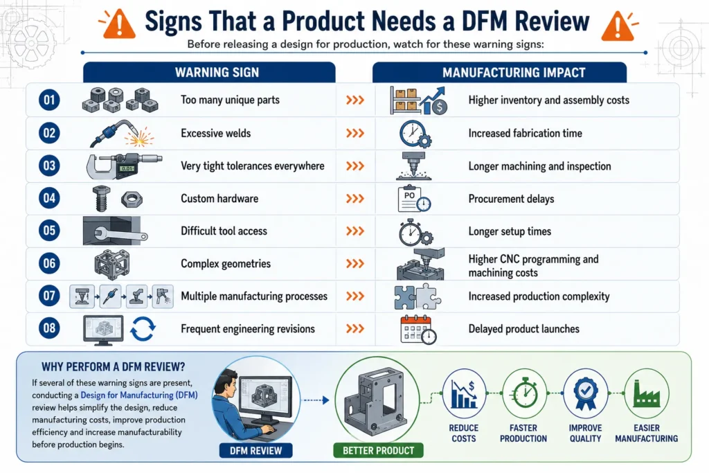
One of the most common DFM mistakes is applying unnecessarily tight tolerances throughout a design.
For example:
Instead of specifying ±0.02 mm for every feature, engineers should reserve precision tolerances only for critical functional dimensions.
Relaxing non-critical tolerances allows manufacturers to:
- Use standard machining processes
- Reduce inspection time
- Improve production speed
- Lower manufacturing costs
4. Number of Components
Every additional part introduces:
- Manufacturing cost
- Inventory management
- Procurement effort
- Assembly labor
- Inspection requirements
- Documentation complexity
Reducing part count through intelligent design often delivers significant cost savings throughout the product lifecycle.
5. Manufacturing Process Selection
A design optimized for CNC machining may not be suitable for sheet metal fabrication.
Similarly, a casting-friendly design differs significantly from one intended for additive manufacturing.
Selecting manufacturing processes early helps engineers design parts that align with available production capabilities.
The Business Benefits of Design for Manufacturing
Implementing DFM delivers measurable benefits across engineering, manufacturing, procurement, and quality departments.
1. Lower Manufacturing Cost
Simplified designs reduce:
- Machining hours
- Material waste
- Tool wear
- Welding operations
- Fabrication complexity
- Assembly labor
Lower production effort directly reduces manufacturing costs.
2. Faster Time-to-Market
Designs requiring fewer engineering revisions move through production more quickly.
Benefits include:
- Faster prototype development
- Shorter production planning
- Reduced tooling modifications
- Quicker product launches
3. Improved Product Quality
Products designed with manufacturability in mind generally exhibit:
- Better dimensional consistency
- Fewer production defects
- Reduced assembly errors
- Improved repeatability
Consistent manufacturing processes produce more reliable products.
4. Reduced Engineering Changes
Late-stage design changes are expensive.
DFM minimizes:
- Design revisions
- Prototype failures
- Production interruptions
- Manufacturing rework
This reduces project delays and engineering costs.
5. Easier Assembly
DFM often works alongside Design for Assembly (DFA) to simplify product assembly.
Benefits include:
- Fewer assembly steps
- Reduced labor time
- Lower risk of installation errors
- Improved production throughput
6. Better Supply Chain Efficiency
Standardized components simplify procurement.
Benefits include:
- Lower inventory costs
- Easier sourcing
- Improved supplier flexibility
- Reduced lead times
Core Principles of Design for Manufacturing
Successful DFM is built on a series of engineering principles that guide design decisions throughout product development.
1. Simplify Product Design
The simplest design is often the most economical.
Engineers should eliminate unnecessary:
- Features
- Parts
- Welds
- Fasteners
- Manufacturing operations
Simplification reduces both production cost and manufacturing risk.
2. Reduce Part Count
Each additional component introduces manufacturing and assembly costs.
Where practical:
- Combine multiple parts.
- Use multifunctional components.
- Design self-locating features.
- Minimize brackets and adapters.
Reducing part count also improves product reliability by decreasing the number of potential failure points.
3. Standardize Components
Using standard components instead of custom-designed parts offers several advantages:
- Lower procurement costs
- Faster sourcing
- Simplified inventory management
- Easier maintenance
- Reduced engineering effort
Examples include:
- Standard fasteners
- Bearings
- Hinges
- Bushings
- Linear guides
- Purchased hardware
4. Design Around Manufacturing Processes
Every manufacturing process has unique capabilities and limitations.
Designs should accommodate the chosen process rather than forcing manufacturers to overcome unnecessary complexity.
For example:
- Sheet metal parts should use practical bend radii and standard bend angles.
- CNC-machined components should avoid inaccessible internal corners.
- Weldments should allow proper welding access.
- Injection-molded parts should include draft angles for mold release.
Aligning the design with the manufacturing method reduces production challenges and improves consistency.
5. Use Appropriate Tolerances
Precision should only be specified where it directly affects product performance.
Applying unnecessarily tight tolerances to every feature increases machining time, inspection effort, and manufacturing cost without adding value.
A balanced tolerance strategy ensures quality while maintaining production efficiency.
Applying Design for Manufacturing Across Different Manufacturing Processes
Every manufacturing process has its own capabilities, limitations, tolerances, and cost drivers. A design optimized for one process may be difficult,or even impossible,to manufacture using another.
One of the primary objectives of DFM is to align the product design with the intended manufacturing process from the earliest stages of development.
Applying Design for Manufacturing principles during our Sheet Metal Design Services helps reduce bends, welding, and production costs while improving manufacturability.
Design for Manufacturing in Sheet Metal Design
Sheet metal is widely used for industrial enclosures, electrical cabinets, laboratory furniture, machine guards, storage systems, HVAC equipment, and fabrication projects because it offers an excellent balance of strength, weight, and cost.
However, poorly designed sheet metal parts can significantly increase production costs.
Common Sheet Metal Design Mistakes
Engineers frequently encounter issues such as:
- Excessive number of bends
- Extremely small bend radii
- Non-standard hole sizes
- Holes placed too close to bends
- Numerous welded brackets
- Difficult-to-reach welding locations
- Excessive hardware requirements
- Overly complex formed features
Each of these design choices increases fabrication complexity.
For example:
A simple enclosure requiring four bends can often be fabricated in a single setup.
The same enclosure redesigned with twelve bends, multiple welded brackets, and several secondary machining operations may require:
- Multiple press brake setups
- Additional welding fixtures
- Longer inspection times
- Higher labor costs
- Increased risk of dimensional inaccuracies
DFM Best Practices for Sheet Metal
1. Use Standard Material Thicknesses
Standard sheet gauges are readily available from suppliers and generally reduce procurement costs.
Choosing uncommon thicknesses may result in:
- Longer lead times
- Higher material prices
- Minimum order requirements
2. Minimize the Number of Bends
Every bend requires:
- Machine setup
- Press brake operation
- Inspection
- Potential rework
Reducing unnecessary bends shortens manufacturing time while improving consistency.
3. Design with Appropriate Bend Radii
Using recommended bend radii helps prevent:
- Material cracking
- Spring-back issues
- Forming defects
Standard bend tooling can also be used more efficiently.
4. Maintain Hole-to-Bend Clearance
Placing holes too close to bends often causes distortion after forming.
Proper clearance minimizes:
- Secondary machining
- Dimensional variation
- Scrap rates
5. Reduce Welding Wherever Possible
Replacing welded assemblies with folded sheet metal designs often results in:
- Lower fabrication cost
- Better dimensional consistency
- Reduced distortion
- Faster production
6. Standardize Fasteners
Using one or two fastener sizes throughout a product simplifies:
- Procurement
- Assembly
- Inventory management
- Maintenance
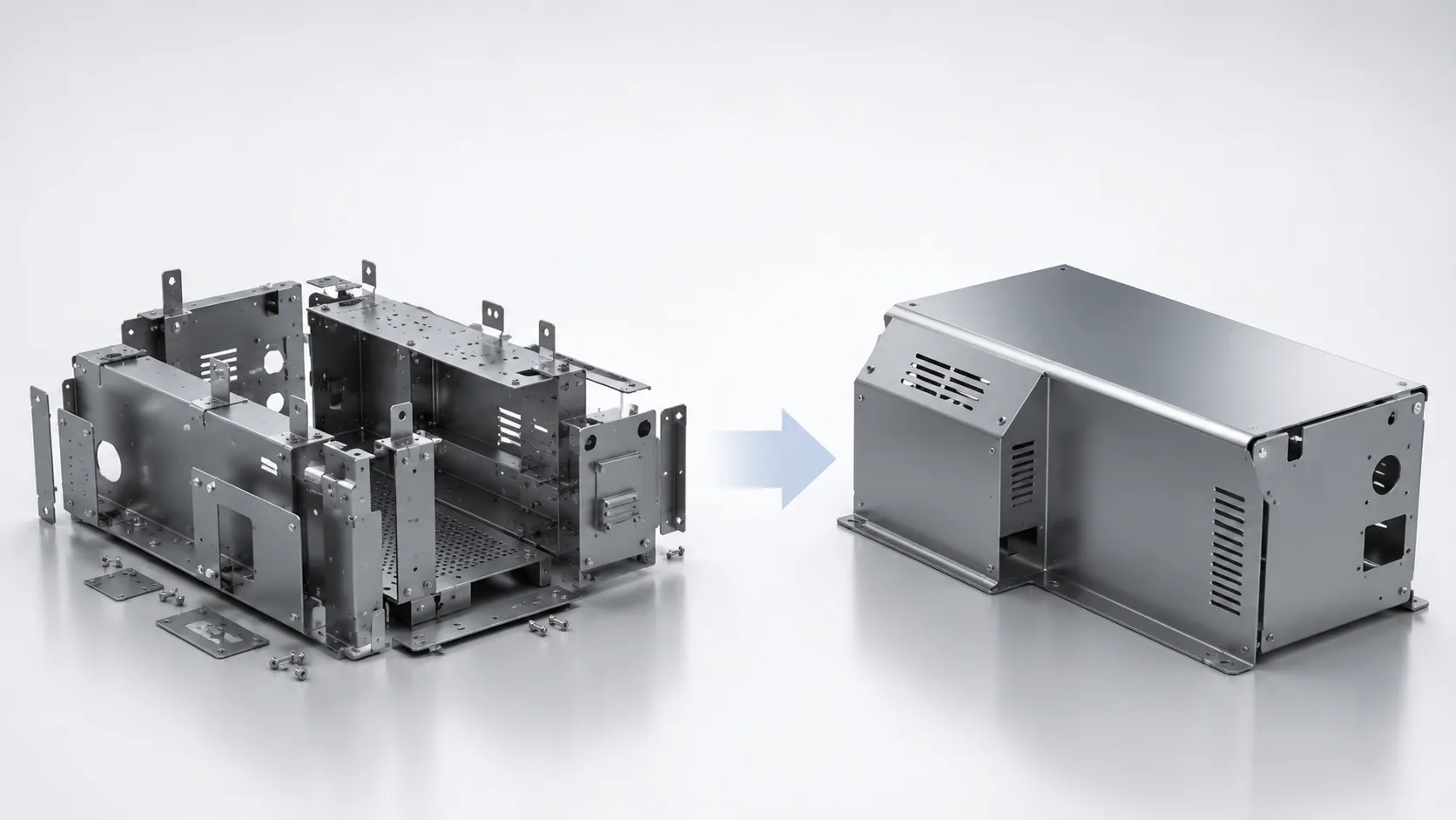
Example: Sheet Metal DFM Improvement
Original Design
- 18 fabricated components
- 42 spot welds
- 14 unique fasteners
- Multiple custom brackets
Optimized DFM Design
- 11 fabricated components
- Integrated folded features
- 6 standard fasteners
- Reduced welding operations
Although both products perform the same function, the optimized design requires fewer manufacturing operations and is easier to assemble.
Features That Increase Machining Cost
Examples include:
- Deep narrow pockets
- Tiny internal radii
- Extremely tight tolerances
- Thin unsupported walls
- Complex freeform surfaces
- Blind pockets requiring specialized tooling
- Multiple setups
Each additional machining operation increases:
- Programming time
- Machine cycle time
- Tool wear
- Inspection effort
DFM Best Practices for Machined Parts
1. Avoid Unnecessarily Tight Tolerances
Precision machining is expensive.
Specify tight tolerances only where required for:
- Bearing fits
- Shaft alignment
- Sealing surfaces
- Critical assemblies
General features can usually accommodate standard machining tolerances.
2. Use Standard Tool Sizes
Designing pockets and slots around standard cutter diameters avoids custom tooling and reduces machining time.
3. Add Internal Corner Radii
Cutting perfectly sharp internal corners requires electrical discharge machining (EDM) or additional finishing operations.
Using realistic corner radii allows standard end mills to machine the feature efficiently.
4. Reduce Machining Depth
Deep cavities require:
- Longer cutting tools
- Reduced cutting speeds
- Additional passes
Shallower features are generally easier and faster to manufacture.
5. Simplify Part Geometry
Removing cosmetic or unnecessary features reduces programming complexity while improving machining efficiency.
Example: Machining Optimization
A support bracket originally contained:
- 16 drilled holes
- Four different hole diameters
- Five pocket depths
After DFM review:
- Hole sizes were standardized.
- Pocket depths were simplified.
- Non-functional features were removed.
The redesigned part required fewer tool changes and significantly shorter machining cycles.
Design for Manufacturing in Weldments and Fabricated Structures
Fabricated assemblies are common in:
- Industrial machinery
- Structural frames
- Skids
- Platforms
- Conveyor systems
- Material handling equipment
Although welding is flexible, excessive welding often increases manufacturing costs more than expected.
Common Weldment Design Issues
Poor weldment designs frequently include:
- Too many welded joints
- Difficult welding access
- Large weld sizes where unnecessary
- Excessive fixturing
- Complex joint geometries
These factors increase:
- Fabrication time
- Heat distortion
- Grinding
- Inspection requirements
DFM Guidelines for Weldments
1. Design for Welding Access: Ensure welders can comfortably access all joints.
Poor accessibility increases:
- Labor hours
- Welding defects
- Safety risks
2. Use Standard Structural Sections: Whenever possible, specify commonly available:
- Square tubes
- Rectangular tubes
- Channels
- Angles
- Standard pipe sizes
Standard profiles reduce procurement challenges.
3. Minimize Weld Length: Long welds increase:
- Heat input
- Distortion
- Consumable usage
- Labor
Design only the weld length necessary for structural performance.
4. Design Self-Locating Components: Tabs, slots, and locating features reduce fixture complexity while improving assembly accuracy.
5. Standardize Joint Types:Using consistent joint designs throughout the product simplifies fabrication procedures and welder training.
Well-designed Jigs and Fixtures Design Services improve part positioning, reduce setup time, enhance welding accuracy, and ensure consistent dimensional quality during fabrication and assembly.
Example: Weldment Optimization
An equipment skid originally required:
- 64 welded joints
- Six custom fixtures
- Extensive post-weld grinding
Following DFM improvements:
- Joint count reduced by 30%
- Standard profiles introduced
- Weld accessibility improved
- Grinding operations minimized
The result was lower fabrication time and improved dimensional consistency.
Design for Manufacturing for Assemblies
Individual parts may be well designed, yet the complete product may still be difficult to manufacture.
Assembly should be considered during product development.
Questions engineers should ask include:
- Can components be assembled in one direction?
- Are fasteners easily accessible?
- Can parts only fit in the correct orientation?
- Is assembly intuitive?
- Can maintenance be performed easily?
Simplified assembly reduces production time while minimizing assembly errors.
Engineering Review Questions Before Production:
Before releasing drawings, engineering teams should evaluate the following:
1. Materials
- Is this the most suitable material?
- Is it readily available?
- Can a lower-cost alternative provide the same performance?
2. Manufacturing Process
- Is the selected manufacturing method appropriate?
- Can production be simplified?
3. Geometry
- Can unnecessary features be removed?
- Can part count be reduced?
- Are machining operations minimized?
4. Standardization
- Are standard components used wherever possible?
- Can hardware be consolidated?
5. Assembly
- Is the assembly sequence simple?
- Can operators assemble the product without special tools?
6. Inspection
- Can critical dimensions be inspected easily?
- Are tolerances practical?
By now, we’ve covered the fundamentals of Design for Manufacturing (DFM), its core principles, and how it applies across sheet metal fabrication, machining, weldments, and molded components. In this final section, we’ll look at how modern engineering tools support DFM, how to conduct an effective DFM review, common mistakes to avoid, and practical ways manufacturers can implement DFM to improve product quality while reducing production costs.
How CAD and Digital Engineering Improve Design for Manufacturing
Modern product development extends beyond creating a 3D model. Advanced CAD platforms enable engineers to evaluate manufacturability before production begins, allowing design issues to be resolved digitally rather than on the shop floor.
Instead of relying on physical prototypes to identify manufacturing challenges, engineering teams can use digital tools to optimize designs early in the development cycle.
1. Parametric CAD Modeling
Parametric CAD software allows dimensions, features, and design rules to update automatically when changes are made.
This helps engineers:
- Evaluate multiple design alternatives quickly
- Standardize product families
- Reduce manual redesign
- Minimize engineering errors
- Support configurable products
For manufacturers producing multiple product variants, parametric modeling significantly reduces engineering effort while maintaining consistency.
2. Automated Manufacturing Drawings
Generating production drawings manually is time-consuming and increases the likelihood of inconsistencies.
CAD automation can streamline tasks such as:
- Drawing generation
- Bill of Materials (BOM) creation
- DXF export for laser cutting
- Flat pattern generation
- Revision management
- Custom property updates
Many manufacturers also leverage SolidWorks API & VBA Automation to automate repetitive engineering tasks such as drawing generation, BOM creation, DXF exports, flat-pattern generation, and custom property management, allowing engineers to spend more time optimizing manufacturability
3. Interference and Clearance Checks
One of the most common causes of manufacturing rework is component interference.
Digital assembly validation helps engineers detect:
- Part collisions
- Assembly constraints
- Fastener accessibility issues
- Maintenance clearance problems
- Motion interference
Identifying these issues before fabrication reduces costly engineering changes later.
4. Design Validation Through Simulation
Simulation tools allow engineers to evaluate product performance without manufacturing physical prototypes.
Common analyses include:
- Structural stress analysis
- Deflection studies
- Thermal analysis
- Fatigue assessment
- Motion simulation
- Load distribution
Simulation supports DFM by ensuring that simplified, cost-effective designs continue to meet functional requirements.
The Design for Manufacturing Review Process
A successful DFM review is a collaborative activity involving engineering, manufacturing, procurement, and quality teams.
Rather than evaluating manufacturability after drawings are released, DFM should be integrated into the product development process.
Step 1: Review Product Functionality
Confirm that every feature contributes to the product’s intended function.
Questions to ask include:
- Does this feature provide measurable value?
- Can two parts be combined?
- Is every machining operation necessary?
Step 2: Evaluate Material Selection
Review whether the selected material:
- Meets performance requirements
- Is readily available
- Supports the intended manufacturing process
- Can be replaced with a lower-cost alternative
Material optimization often delivers immediate cost savings.
Step 3: Review Manufacturing Processes
Determine whether each manufacturing process is appropriate.
Examples include:
- CNC machining
- Laser cutting
- Bending
- Welding
- Casting
- Injection molding
- Additive manufacturing
The objective is to minimize process complexity without compromising product quality.
Step 4: Simplify Assembly
Review the complete assembly sequence.
Look for opportunities to:
- Reduce fasteners
- Eliminate unnecessary brackets
- Improve accessibility
- Standardize hardware
- Reduce assembly time
Step 5: Validate Inspection Requirements
Quality inspection should be practical and efficient.
Review:
- Critical dimensions
- Datum structure
- Measurement accessibility
- Tolerance stack-up
- Inspection equipment requirements
Common Design for Manufacturing Mistakes
Even experienced engineering teams can unintentionally introduce manufacturing inefficiencies.
Recognizing these issues early helps avoid unnecessary production costs.
1. Over-Engineering Components
Products are often designed with features that exceed functional requirements.
Examples include:
- Extremely tight tolerances
- Oversized welds
- Excessively thick materials
- Unnecessary cosmetic machining
Simplifying these features can significantly reduce manufacturing costs.
2. Designing Without Manufacturing Input
Engineering teams sometimes finalize designs before consulting production personnel.
This can lead to:
- Difficult fabrication
- Inefficient tooling
- Long setup times
- Assembly challenges
Involving manufacturing engineers early improves design decisions.
3. Ignoring Standard Components
Custom-designed hardware increases:
- Procurement costs
- Lead times
- Inventory complexity
Standard components simplify production and maintenance.
4. Excessive Product Variations
Creating numerous unique components for similar products increases:
- Engineering workload
- Inventory management
- Manufacturing complexity
Standardization improves scalability.
Designing Around CAD Rather Than Manufacturing
A CAD model can appear perfect while remaining difficult to fabricate.
Effective DFM requires engineers to think beyond the digital model and consider how the product will actually be manufactured.
Industry Applications of Design for Manufacturing
Although DFM principles are universal, their implementation varies by industry.
1. Industrial Equipment
DFM helps reduce fabrication complexity for:
- Machine frames
- Process skids
- Conveyors
- Material handling systems
Benefits include:
- Lower fabrication costs
- Faster assembly
- Improved structural consistency
2. Sheet Metal Products
Applications include:
- Electrical enclosures
- Control panels
- Laboratory furniture
- Server cabinets
- Industrial workstations
DFM focuses on:
- Bend optimization
- Standard hardware
- Reduced welding
- Material utilization
3. Process Equipment
Pressure vessels, heat exchangers, tanks, and piping systems benefit from:
- Optimized weld design
- Standard nozzle configurations
- Improved fabrication sequences
- Reduced inspection effort
4. Automation Equipment
Machine builders use DFM to simplify:
- Structural assemblies
- Motion systems
- Safety guarding
- Equipment installation
Reducing component count improves manufacturing and maintenance.
5. Consumer Products
For high-volume production, DFM helps optimize:
- Plastic molding
- Die casting
- Machining
- Product assembly
Even small design improvements can result in substantial cost savings across large production volumes.
How Immersiv Techsphere Supports Design for Manufacturing
Successful DFM requires a combination of engineering expertise, manufacturing knowledge, and digital design capabilities.
At Immersiv Techsphere, our engineering team works with manufacturers to develop production-ready designs that balance functionality, manufacturability, and cost efficiency.
Our Design for Manufacturing approach includes:
- Mechanical product design
- Sheet metal design optimization
- Weldment and fabrication design
- Manufacturing-ready CAD models
- Production drawings
- CAD automation
- Design standardization
- Product engineering support
- Engineering change implementation
- Prototype-to-production assistance
By evaluating manufacturability early in the product development cycle, manufacturers can reduce engineering revisions, improve production efficiency, and accelerate product launches.
Frequently Asked Questions (FAQs)
DFM helps manufacturers reduce material waste, simplify fabrication, shorten production cycles, improve product consistency, and lower overall manufacturing costs.
DFM should begin during the early design stage and continue throughout product development. Identifying manufacturing challenges before production is significantly more cost-effective than making changes after tooling or fabrication has started.
DFM reduces manufacturing cost by minimizing unnecessary machining, simplifying assemblies, reducing part count, standardizing components, optimizing material selection, and improving production efficiency.
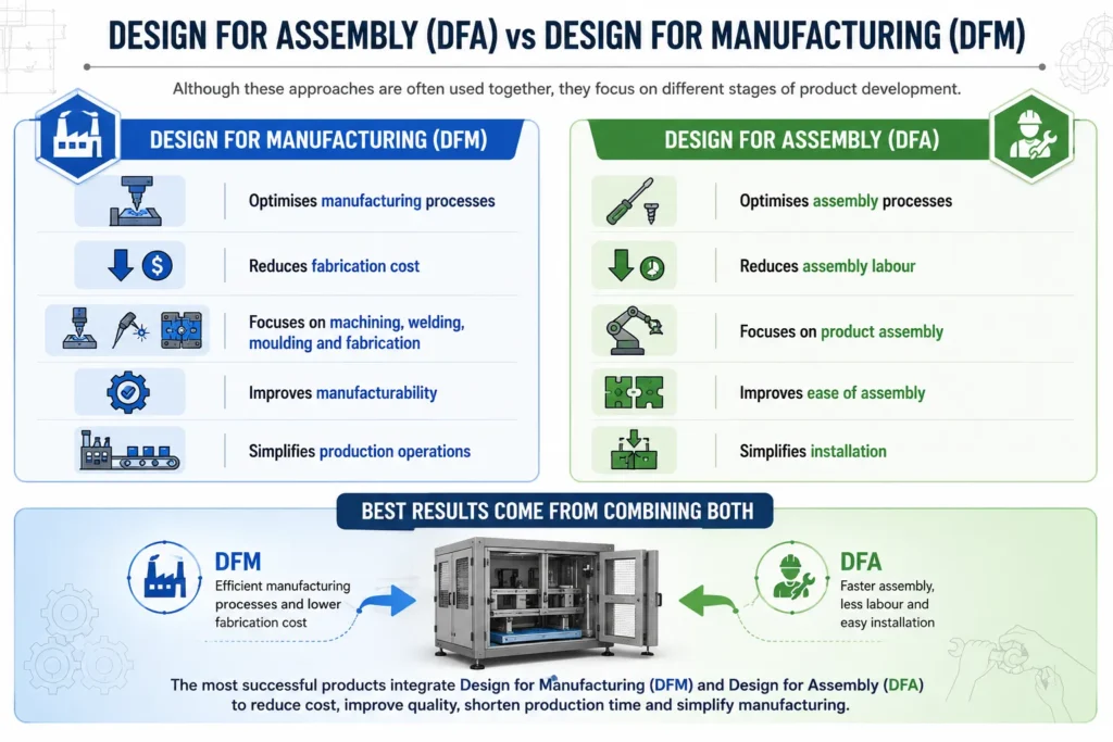
Design for Manufacturing (DFM) focuses on simplifying fabrication processes, while Design for Assembly (DFA) focuses on making products easier and faster to assemble. Together, they reduce overall production cost.
Common tools include SolidWorks, Autodesk Inventor, Siemens NX, CATIA, Creo, Fusion 360, AutoCAD, and simulation software for structural and manufacturing validation.
No. DFM benefits both low-volume custom products and high-volume manufacturing by improving efficiency, reducing costs, and simplifying production processes.
Yes. Optimized designs often require fewer materials, generate less scrap, consume less energy during production, and reduce waste throughout the product lifecycle.
Absolutely. Existing products can be reviewed and redesigned to reduce manufacturing complexity, improve quality, lower production costs, and simplify assembly.
Conclusion
Design for Manufacturing is far more than a cost-reduction technique, it is a strategic engineering approach that influences the success of a product long before manufacturing begins. The decisions made during design determine material utilization, fabrication complexity, assembly efficiency, product quality, and ultimately the total cost of production.
By integrating DFM principles early in the product development process, manufacturers can simplify designs, reduce unnecessary operations, standardize components, and create products that are easier to build, inspect, maintain, and scale. These improvements lead to lower manufacturing costs, shorter lead times, better quality, and greater competitiveness in today’s demanding industrial landscape.
Whether you’re developing sheet metal enclosures, industrial machinery, laboratory furniture, fabricated structures, or automation equipment, investing in manufacturability during the design phase delivers measurable benefits throughout the product lifecycle.
Engineering excellence is not only about designing products that work,it’s about designing products that can be manufactured efficiently, consistently, and economically. Organizations that embrace Design for Manufacturing gain a significant advantage by reducing waste, accelerating production, and delivering higher-value products to their customers.
Have a Project in Mind?
Need help with 3D animation, industrial visualization, HSE training animation, or product visualization? Tell us about your project and our team will get back to you.