

Table of Contents
Introduction
A 3D CAD model may look perfect on screen, but does it fit correctly when assembled? Are the mounting holes aligned? Is there enough clearance between moving components? These are questions that often come up when a product moves from digital design towards manufacturing.
Identifying these issues during the design stage can help avoid unnecessary modifications later. However, relying only on digital models may not always be enough to evaluate the physical dimensions, assembly arrangement and usability of a product.
This is where rapid prototyping using 3D printing becomes useful.
Rapid prototyping using 3D printing offers a practical way to accelerate this process. It allows designers and engineers to transform digital models into physical parts, evaluate their designs and make improvements before committing to final manufacturing.
From simple concept models to detailed mechanical components, 3D printing supports different stages of product development. Companies can use it to assess product appearance, check assembly fit, test selected functional characteristics and communicate design concepts to stakeholders.
By incorporating rapid prototyping into product development, businesses can make design decisions earlier, reduce avoidable rework and improve collaboration between design, engineering and manufacturing teams.
What Is Rapid Prototyping Using 3D Printing?
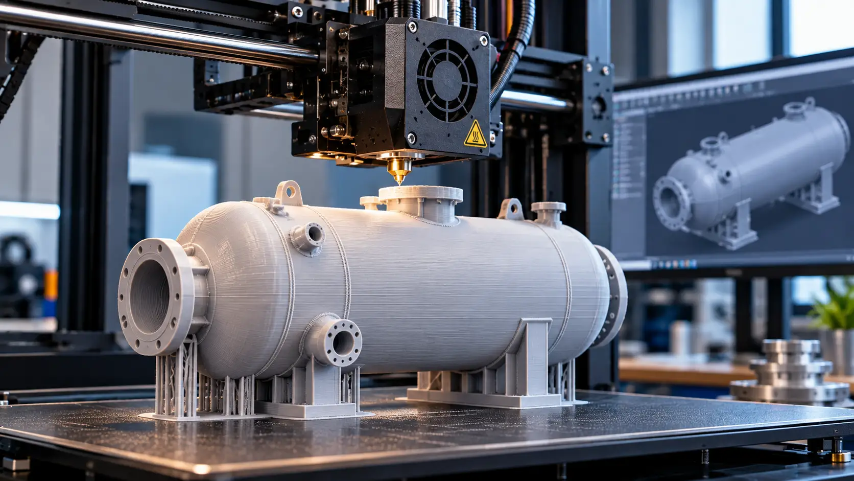
Rapid prototyping using 3D printing is the process of creating physical models or components directly from digital 3D designs so that products can be evaluated and improved before production.
- Faster conversion of CAD models into physical prototypes.
- Easier design modifications and repeated iterations.
- Reduced dependence on dedicated tooling during early development.
- Improved visualization of shape, dimensions and assembly.
- Earlier identification of design and manufacturing issues.
- Support for customized parts and complex geometries.
The most suitable approach depends on the prototype’s purpose, required material properties, dimensional tolerances, surface finish, budget and delivery schedule.
Understanding the Role of Rapid Prototyping in Product Development
What Does Rapid Prototyping Actually Mean?
Rapid prototyping is a product development approach in which physical models are produced quickly so that a proposed design can be examined before it is finalized.
3D printing is one of the technologies used for this purpose. It belongs to additive manufacturing, in which a component is built by adding material progressively according to digital design data. The ISO/ASTM 52900 standard establishes terminology and fundamental concepts for additive manufacturing.
3D printing is one of the commonly used methods for this purpose. It uses additive manufacturing technology, where material is deposited or consolidated layer by layer to create a physical component based on a digital 3D model.
Unlike some conventional prototyping methods that require dedicated tooling or machining setups, 3D printing can produce suitable prototype geometries directly from prepared CAD data.
Depending on the development stage, prototypes can be used to evaluate:
- Overall product shape, dimensions and appearance.
- Component positioning and assembly arrangements.
- Mounting holes, slots and connection points.
- Clearances between mating or moving components.
- Ergonomics and accessibility.
- Selected functional characteristics, when the material and printing process are suitable.
The purpose of a prototype should be defined before selecting the printing technology or material. A model created to check appearance may have different requirements from one intended for assembly evaluation or mechanical testing.
Why Do Engineers Need Physical Prototypes?
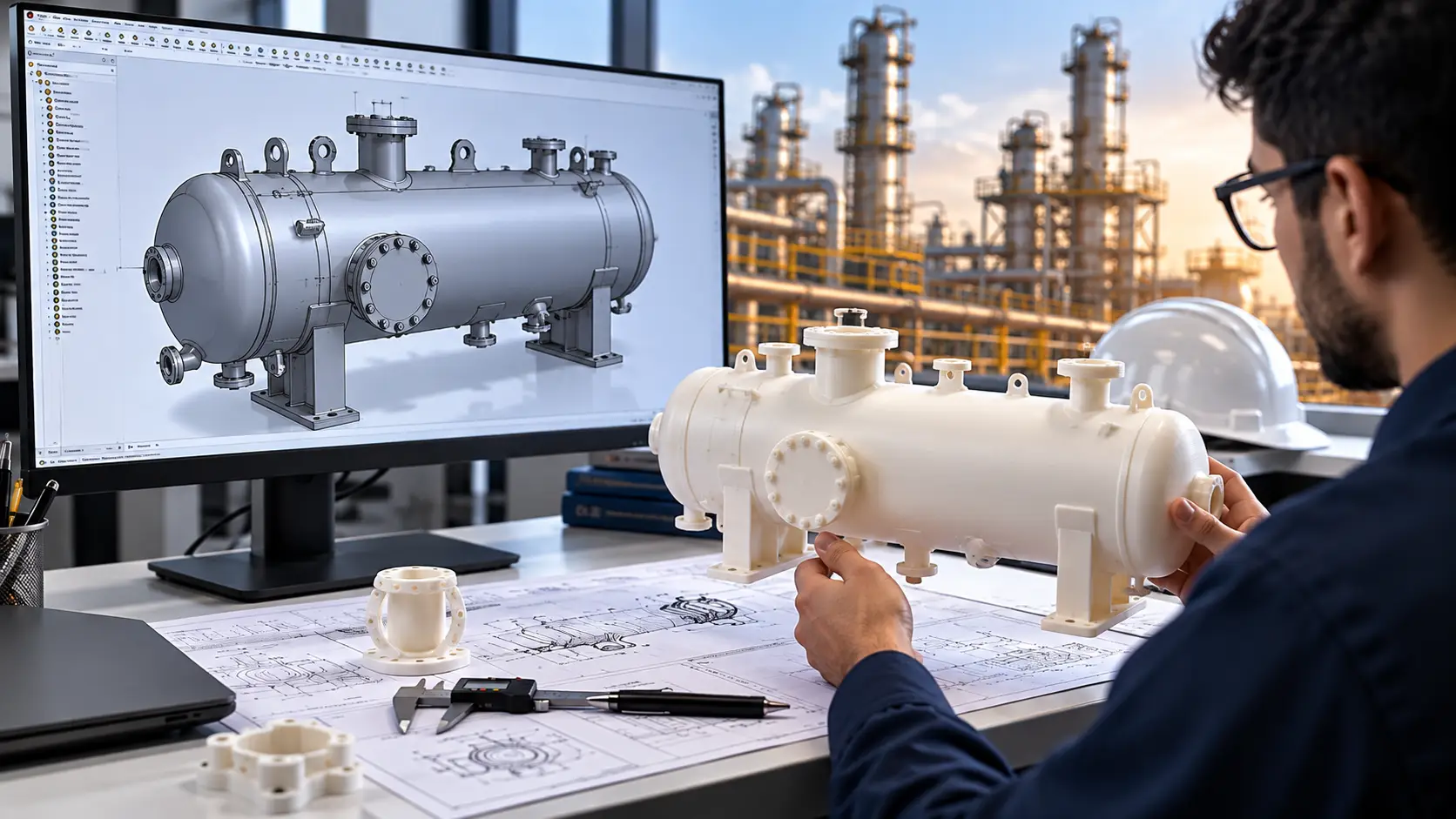
A digital model can communicate dimensions and geometry, but a physical prototype allows teams to inspect the design from different angles, assemble components, handle the product and evaluate selected functional requirements.
Prototyping can help answer questions such as:
- Does the component fit within the available space?
- Can two parts be assembled correctly?
- Are mounting holes and connection points positioned correctly?
- Is the product comfortable or convenient to use?
- Are there any visible design issues?
- Does the design need changes before production?
Different Types of Prototypes Used in Product Development
- Concept prototypes: Used to communicate an idea, overall shape or product appearance.
- Form prototypes: Used to evaluate dimensions, proportions, ergonomics and visual design.
- Fit prototypes: Used to check mating components, clearances, mounting features and assembly arrangements.
- Functional prototypes: Used to evaluate selected mechanical or operational characteristics under defined conditions.
- Pre-production prototypes: Used to assess a more developed design before transitioning to the intended production method.
Not every prototype must perform every function. A model created to evaluate appearance may require different materials and tolerances from a component intended for mechanical testing.
From CAD Model to Physical Prototype: How the Process Works
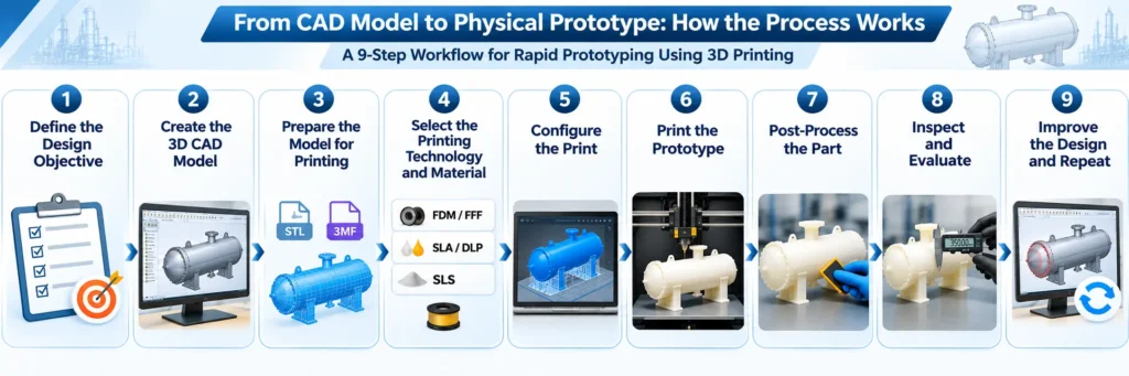
- Define the design objective: Determine what the prototype must demonstrate. This may include appearance, dimensions, fit, ergonomics, assembly or selected functional characteristics.
- Create the 3D CAD model: Design the component using suitable CAD software. Include the required dimensions, mounting features, holes, wall thicknesses, clearances and other design details.
- Prepare the model for printing: Export the model into a suitable file format, such as 3MF or STL, depending on the software and workflow. Check the geometry for errors and confirm that the model has the correct dimensions and orientation.
- Select the printing technology and material: Choose a process according to the prototype’s purpose, required accuracy, surface finish, strength and budget.
- Configure the print: Prepare the model in slicing or build-preparation software. Set parameters such as layer height, infill, wall count, support structures and orientation where applicable.
- Print the prototype: The printer builds the physical component according to the prepared digital instructions. Print duration varies with part size, geometry, layer settings, material and machine capabilities.
- Post-process the part: Depending on the technology, post-processing may include support removal, washing, curing, sanding, surface finishing or other specified procedures.
- Inspect and evaluate: Compare the printed component with the design requirements. Check dimensions, fit, appearance, assembly and the specific functions the prototype was created to evaluate.
- Improve the design and repeat: Document issues, modify the CAD model and produce another iteration when necessary. Continue until the prototype meets the defined development objectives or provides enough evidence to proceed.
How 3D Printing Improves the Product Development Process
- Faster design iterations: A revised CAD model can often be printed without manufacturing new dedicated tooling. This makes it easier to compare design alternatives and refine components.
- Reduced early-stage tooling requirements: Many 3D-printed prototypes can be produced without the molds or dies required for certain conventional manufacturing methods. This can be especially useful when the design is still changing.
- Improved design validation: Physical prototypes help teams identify dimensional conflicts, assembly difficulties and visual issues that may be difficult to assess using a digital model alone.
- Greater design flexibility: Additive manufacturing can produce many complex geometries, internal channels and customized shapes that may be difficult or expensive to create using some traditional processes.
- Better communication: A physical model helps engineers, customers, management teams and other stakeholders discuss a design using a tangible reference.
- Support for customization: Different design variants can often be produced from revised digital files without changing dedicated tooling.
- Potential reduction in development waste: Producing and evaluating a prototype before committing to more expensive production steps can help avoid some unnecessary manufacturing work. The actual cost and material savings depend on the project and process.
Where is Rapid Prototyping Used in Mechanical and Industrial Design?
- Product design and development: Design teams use 3D-printed models to evaluate product proportions, housing shapes, button placement, ergonomics and assembly concepts.
- Automotive engineering: Automotive teams can prototype brackets, dashboard components, sensor housings, ducts, trim pieces and selected assembly aids. Safety-critical parts require appropriate engineering validation.
- Mechanical engineering: Engineers can evaluate component geometry, clearances, mounting arrangements, enclosures and interfaces between mechanical parts.
- Industrial equipment: Prototypes can help validate machine covers, custom fixtures, handles, equipment housings and selected tooling concepts.
- Consumer electronics: 3D printing can support enclosure development, connector placement, internal component packaging and external appearance reviews.
- Architecture and product visualization: Physical models can help teams communicate complex shapes, spatial arrangements and design concepts.
- Healthcare and medical device development: Suitable printing processes can be used to create anatomical models and prototypes for design evaluation. Medical applications may require specific materials, validation and regulatory controls.
- Manufacturing aids: Companies can prototype jigs, fixtures, assembly guides and other production aids before implementing them in the manufacturing environment.
3D Printing vs Traditional Prototyping: Which Method Should You Choose?
The best method depends on the component, quantity, materials and required performance.
| Factor | 3D printing | Traditional prototyping |
|---|---|---|
| Initial setup | Often relatively simple for suitable geometries | May require specialized setup, fixtures or tooling |
| Design changes | Usually made by revising the digital model | May require changes to tooling, machining plans or fixtures |
| Complex geometry | Can produce many intricate shapes | Complexity may increase machining or tooling difficulty |
| Material options | Depends on the selected printing technology | Broad range of manufacturing materials and processes |
| Surface finish | May require post-processing | Depends on the process and finishing method |
| Dimensional accuracy | Depends on technology, material, orientation and settings | Depends on the manufacturing process and equipment |
| Production quantities | Useful for prototypes and selected low-volume parts | Often advantageous for certain larger production runs |
| Mechanical properties | Depend on material, process and build direction | Depend on the material and manufacturing method |
3D printing is not automatically faster or cheaper for every project. For simple components that are easy to machine, conventional manufacturing may be more appropriate. For products requiring frequent design changes or complex geometries, 3D printing can offer significant advantages.
Building an Effective CAD-to-Prototype Workflow
Phase 1: Start with Clear Design Requirements
- Define the purpose of the prototype.
- Identify critical dimensions and interfaces.
- Establish budget and delivery expectations.
- Determine what must be evaluated.
Phase 2: Develop and Review the CAD Model
- Create or update the CAD model.
- Verify dimensions and assembly relationships.
- Review wall thicknesses and design features.
- Prepare alternative versions if comparisons are required.
Phase 3: Choose the Right Prototyping Approach
- Select a suitable printing process.
- Choose a material appropriate to the evaluation.
- Determine build orientation and support requirements.
- Estimate material usage and production time.
Phase 4: Prepare and Produce the Prototype
- Prepare the print file.
- Produce the component.
- Complete required post-processing.
- Record relevant process settings.
Phase 5: Inspect and Evaluate the Physical Model
- Inspect the physical component.
- Compare it with the CAD model and requirements.
- Test fit, assembly or selected functions.
- Record any defects or changes required.
Phase 6: Refine the Design Before Production
- Update the design.
- Print and evaluate the revised component.
- Confirm that acceptance criteria are met.
- Document the final design and decide whether further testing or production preparation is required.
CAD Software, Printing Technologies and Materials Used in Prototyping
Creating Accurate 3D CAD Models
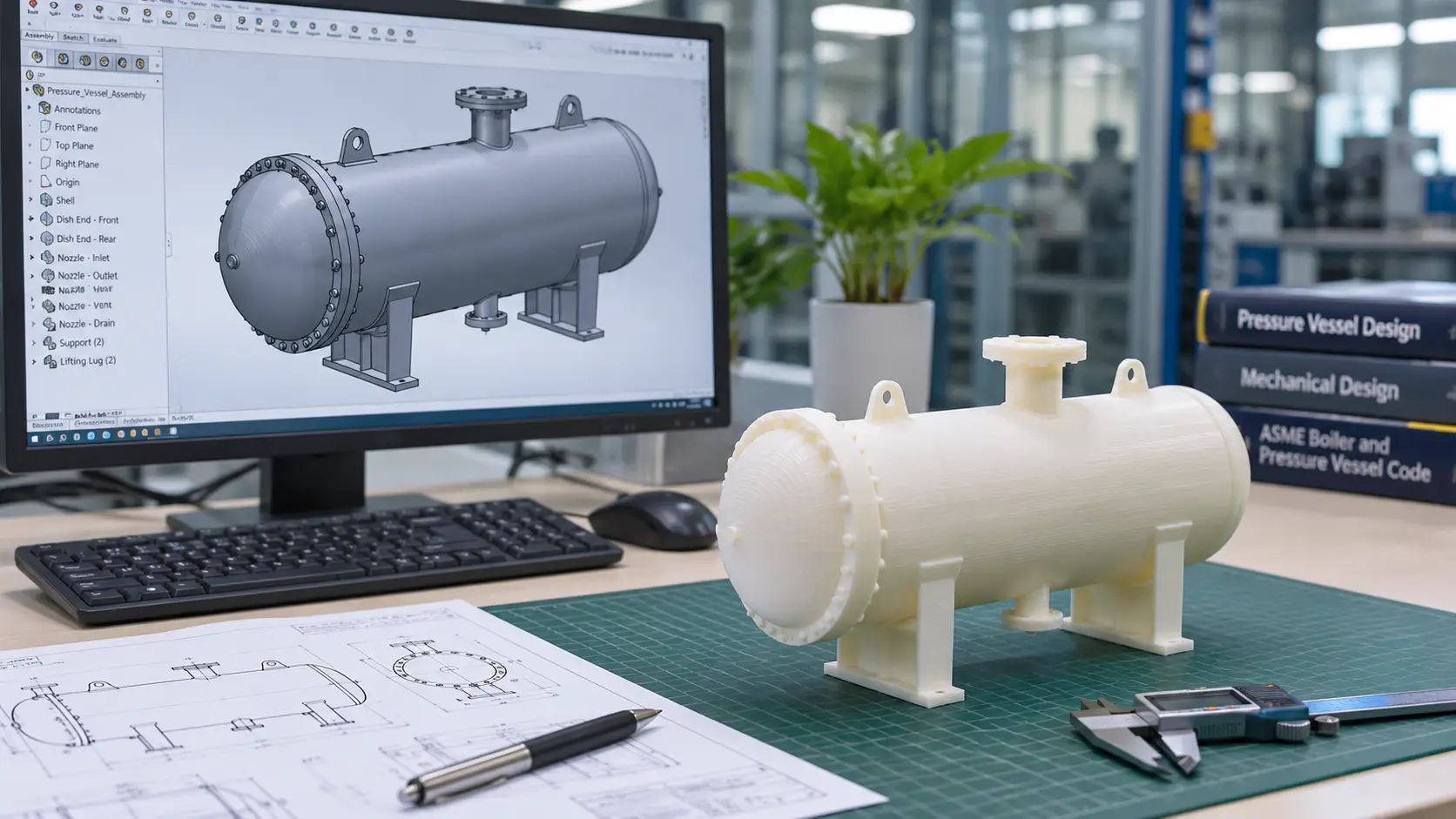
CAD software is used to develop and modify the digital geometry of the prototype. Examples include SolidWorks, Autodesk Fusion, Autodesk Inventor and Blender for suitable visualization and geometry workflows.
Preparing CAD Models for 3D Printing
These tools prepare the model for the selected printer. Examples include Ultimaker Cura, PrusaSlicer and technology-specific preparation software.
Which 3D Printing Technologies Are Used for Prototyping?
- FDM/FFF: Extrudes thermoplastic filament layer by layer.
- SLA/DLP: Uses light to selectively cure liquid photopolymer resin.
- SLS: Uses a laser to fuse material powder, commonly polymer powder.
- Metal additive manufacturing: Uses specialized processes and equipment to produce metal components.
Selecting Materials for Different Prototype Requirements
Materials may include PLA, ABS, PETG, nylon, engineering thermoplastics, photopolymer resins and selected metal powders. Material suitability depends on the application and the specific printing process.
Standards and Technical References
- ISO/ASTM 52900:2021: Additive manufacturing: General principles, fundamentals and vocabulary. https://www.iso.org/standard/74514.html
- NIST: Additive Manufacturing / 3D Printing. https://www.nist.gov/mep/additive-manufacturing3d-printing
- Formlabs: Rapid Prototyping. https://formlabs.com/support/Rapid-prototyping/
Applicable standards and testing requirements should be selected according to the part, industry and intended use.
A Practical Example: Developing a Mechanical Enclosure
Consider a company developing a plastic enclosure for an electronic device. The enclosure must accommodate a circuit board, connectors, mounting points and a cover.
Initial challenge: The first CAD design may look correct on screen, but connector clearances, screw locations or internal component spacing may not work as expected in a physical assembly.
Step 1: CAD design
The engineer creates the enclosure model with the required openings, mounting features and cover interface.
Step 2: First prototype
A 3D-printed enclosure is produced to assess overall dimensions and component placement.
Step 3: Fit evaluation
The team checks whether the circuit board fits, connectors align with openings and the cover assembles correctly.
Step 4: Design improvement
If the connector opening is misaligned or the internal clearance is insufficient, the CAD model is revised.
Step 5: Second iteration
A new prototype is printed to evaluate the updated geometry.
Step 6: Validation
The team checks the enclosure against its defined acceptance criteria and identifies any further testing required before production.
Expected outcome: This workflow can help identify design issues before the company invests in production tooling. Actual time and cost savings depend on part complexity, print duration, testing requirements and the number of iterations.
This is an illustrative example, not a documented customer project or a measured result from Immersiv Techsphere.
What Should Engineers Consider Before Creating a Prototype?
- Material limitations: A prototype material may not reproduce the performance of the intended production material. Consider temperature resistance, flexibility, chemical exposure and mechanical loading.
- Dimensional accuracy: Printed dimensions can be affected by material shrinkage, machine calibration, build orientation and process settings. Critical dimensions should be inspected.
- Surface finish: Visible layer lines, support marks and surface texture may require post-processing when appearance is important.
- Mechanical anisotropy: Some printing processes produce parts whose properties differ by build direction. The prototype should be oriented and tested with this limitation in mind.
- Part size: The component must fit within the printer’s usable build volume. Larger designs may need to be divided into sections and assembled.
- Testing limitations: A prototype that fits correctly does not necessarily prove that the final product is safe, durable or ready for production. Functional, environmental and regulatory testing may still be necessary.
- Cost estimation: Costs can include material, machine time, operator effort, post-processing, inspection and repeated iterations. Evaluate the total workflow rather than only the cost of filament or resin.
- Confidentiality and intellectual property: CAD files may contain valuable product information. Businesses should consider file access, transfer methods, storage and confidentiality arrangements when working with external suppliers.
Best Practices for Successful Rapid Prototyping
- Define the objective first. Decide whether the prototype is intended for appearance, fit, assembly or functional evaluation.
- Use the correct level of detail. Avoid unnecessary features when a simple concept model can answer the design question.
- Choose materials carefully. Match material properties to the evaluation requirements.
- Consider print orientation. Orientation can affect support marks, surface finish, strength and dimensional results.
- Check clearances and tolerances. Allow for the capabilities and limitations of the selected printing process.
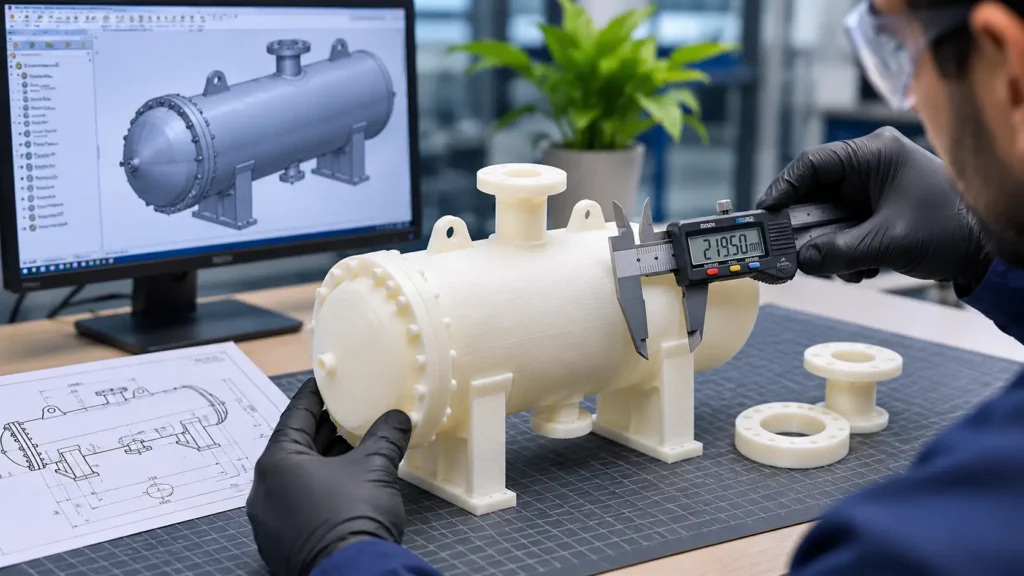
- Inspect the first prototype. Confirm critical dimensions and interfaces before making assumptions about the design.
- Document every iteration. Keep track of CAD revisions, print settings, test results and design decisions.
- Use measurable acceptance criteria. Define what constitutes a successful prototype before testing.
- Plan post-processing. Include finishing and assembly work when estimating delivery time and cost.
- Validate before production. Use the appropriate engineering tests and production-specific checks before approving the final design.
When Does Rapid Prototyping Make Sense for Your Product?
Businesses should consider 3D printing for rapid prototyping when:
- A new product concept needs to be evaluated physically.
- A design requires frequent revisions.
- Assembly fit or component clearance needs verification.
- Several design alternatives must be compared.
- A customized component is required.
- Conventional tooling would be premature for an evolving design.
- Stakeholders need a physical model to review.
- A manufacturing fixture or assembly aid needs to be tested before implementation.
It may be less suitable when a prototype requires material properties that the available printing process cannot provide, extremely high production quantities, or certification and testing beyond the prototype’s intended scope.
A practical approach is to compare 3D printing with machining, casting, molding or other available methods based on the actual design requirements.
How Immersiv Techsphere Supports Mechanical Product Development
Rapid prototyping is most effective when the digital design is prepared carefully before a physical prototype is created. Accurate CAD modelling, well-defined dimensions and properly planned assemblies can make the evaluation process more meaningful.
Immersiv Techsphere supports mechanical product development through 3D CAD modelling, assembly design and manufacturing documentation using tools such as SolidWorks and Autodesk Inventor.
Our engineering team can help businesses develop and refine product models, review component arrangements, incorporate design changes and prepare technical drawings for manufacturing. CAD files can also be prepared in suitable formats, such as STEP or STL, when required for downstream prototyping workflows.
By establishing a structured CAD workflow, businesses can address design considerations earlier and move towards prototype evaluation with better-prepared engineering data.
Frequently Asked Questions
Rapid prototyping in 3D printing is the process of creating physical models from digital 3D designs so that shape, fit, assembly and selected functions can be evaluated before production.
It allows suitable prototypes to be produced directly from revised digital models without creating dedicated tooling for every design iteration. The time saved depends on the part and the workflow.
There is no single best technology for every application. FDM/FFF may suit economical models, resin printing may suit detailed parts, and SLS may suit certain complex functional prototypes. Material requirements and testing objectives should guide the choice.
It can be less expensive for certain low-volume or frequently revised designs because dedicated tooling may not be needed. Conventional methods may be more economical for other parts, so costs should be compared for the specific project.
Yes, when the selected process and material are suitable for the intended test. However, printed parts may differ from production components in strength, durability, temperature resistance and other properties.
A 3D model is generally required. Common formats include STL and 3MF, while the precise format depends on the printer and preparation workflow. The geometry and units should be checked before printing.
The part may require support removal, curing, sanding or other post-processing. It is then inspected and evaluated against the design requirements. If changes are needed, the CAD model is updated and another iteration can be produced.
Conclusion
Rapid prototyping using 3D printing helps engineering teams turn CAD designs into physical components, evaluate design details and identify potential issues before production. From selecting the right printing technology and material to inspecting prototypes and refining designs, each stage contributes to better product development decisions.
A structured CAD-to-prototype workflow can improve design evaluation and manufacturing readiness, particularly for mechanical products, industrial equipment and customized components.
Developing a new product or refining an existing design? Immersiv Techsphere provides 3D CAD modelling, assembly design and manufacturing-ready documentation to support your product development process. Contact our engineering team to discuss your requirements.
Have a Project in Mind?
Need help with 3D animation, industrial visualization, HSE training animation, or product visualization? Tell us about your project and our team will get back to you.