

Table of Contents
Introduction
A detailed 3D CAD model can communicate dimensions, geometry, interfaces, and assembly relationships, but engineers sometimes need to physically evaluate a design before committing it to manufacturing.
This is where 3D printing for product design validation can be useful.
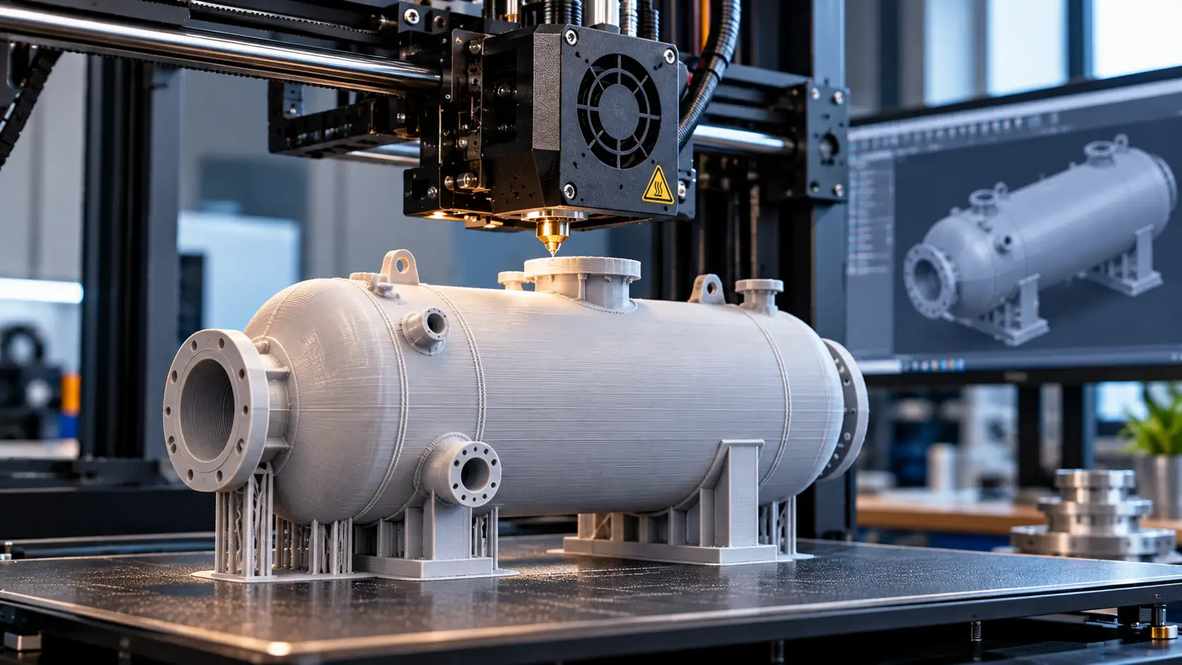
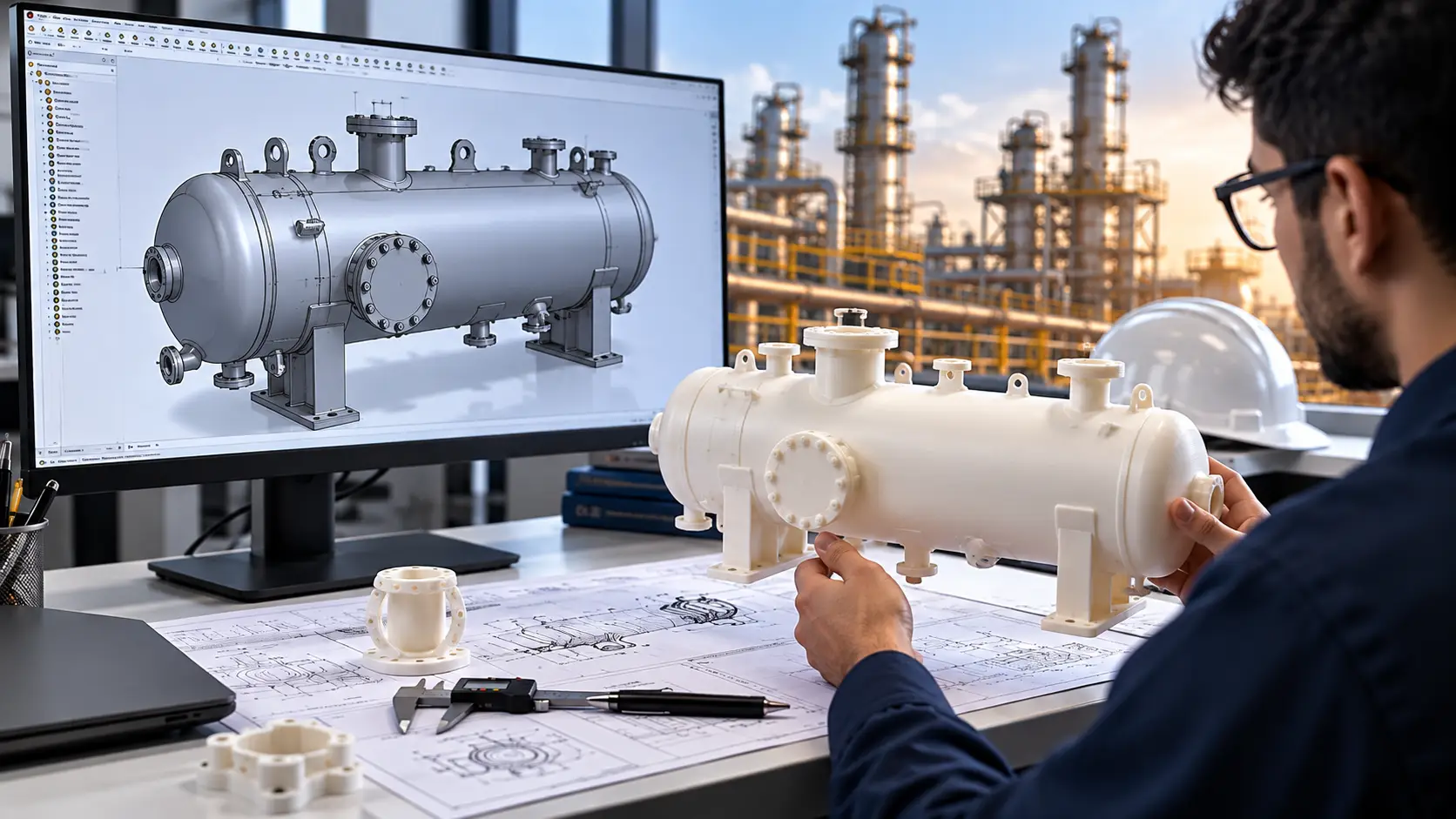
By converting a CAD model into a physical prototype, engineers can examine the actual form of a component or assembly, check interfaces, evaluate accessibility, and identify certain design issues before production tooling, machining, fabrication, or full-scale manufacturing begins.
For mechanical engineering teams, this is particularly valuable when developing components with complex geometry, multiple interfaces, moving parts, or tight packaging requirements.
The principle is straightforward:
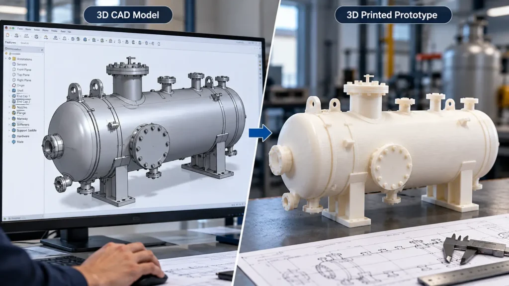
CAD Model → 3D Printed Prototype → Physical Evaluation → Design Revision → Manufacturing
For oil & gas equipment design, the same approach can support early-stage evaluation of components such as equipment housings, brackets, covers, instrument supports, access components, fixtures, and other non-critical prototype parts.
However, a 3D-printed prototype should not automatically be treated as a production-equivalent component. Material properties, printing process, dimensional accuracy, surface finish, anisotropy, temperature resistance, chemical compatibility, pressure resistance, and applicable industry requirements must be considered before using any printed part for functional or service applications. NIST identifies process variability, dimensional accuracy, material properties, and qualification as important considerations in additive manufacturing.
What Is Design Validation Through 3D Printing?
Design validation is the process of checking whether a design satisfies its intended requirements before it moves into manufacturing or final production.
Traditionally, engineers may rely on:
- 3D CAD reviews
- 2D engineering drawings
- Design calculations
- FEA and simulation
- Interference and clearance checks
- Physical prototypes
- Design reviews
- Manufacturing feedback
3D printing adds another useful layer: a physical representation of the CAD design.
Additive manufacturing creates components directly from three-dimensional digital design data. This makes it possible to move relatively quickly from a CAD model to a physical prototype without first producing dedicated tooling for many prototype applications. NIST notes that rapid iterations can help identify design issues earlier while avoiding some of the lead time and cost associated with tooling.
The physical prototype does not replace engineering analysis. Instead, it complements digital validation by allowing engineers to inspect aspects of the design that are easier to understand physically.
Why Mechanical Engineers Use 3D Printed Prototypes
1. Checking Physical Fit and Interfaces
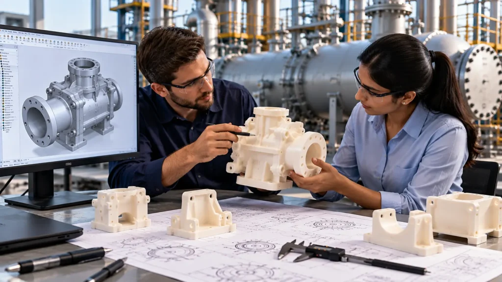
One of the most practical applications is checking whether components physically fit together as intended.
A CAD assembly can indicate that two components have adequate clearance. A printed prototype can provide another way to examine:
- Mounting interfaces
- Hole locations
- Bracket positions
- Fastener access
- Cover clearances
- Component alignment
- Cable or hose routing
- Assembly orientation
- Access around components
For complex mechanical assemblies, this physical check can reveal issues that are easy to overlook during a purely digital review.
For example, an instrument bracket may technically fit within an equipment assembly but leave insufficient space for a technician to access a fastener or connector. A prototype can make this physical constraint immediately apparent.
2. Validating Assembly Sequence and Accessibility
A design may satisfy dimensional requirements but still be difficult to assemble.
A 3D-printed prototype can help engineers evaluate whether:
- Components can be inserted in the intended sequence
- Fasteners can be reached with available tools
- Covers can be installed without interference
- Subassemblies can be positioned correctly
- Operators have adequate access to critical areas
This is particularly relevant to mechanical equipment where several components occupy a compact envelope.
For larger industrial equipment, physical prototypes can be combined with CAD-based assembly reviews and technical visualization. For example, Immersiv Techsphere’s work on 3D assembly animation for heavy industrial equipment demonstrates how digital assembly sequences can also be reviewed before equipment reaches the installation site.
The physical prototype and digital model therefore serve different but complementary purposes.
3. Identifying Ergonomic and Handling Issues
Not every design issue is purely dimensional.
Engineers may also need to understand how a component is handled, accessed, operated, or maintained.
A printed prototype can help evaluate questions such as:
- Is a handle positioned appropriately?
- Can an operator reach a control?
- Is a service cover easy to remove?
- Does the component have sufficient grip?
- Is the overall geometry practical to handle?
- Is there enough access for maintenance?
These evaluations can be especially useful during early product development, when modifying the CAD model is considerably easier than modifying manufactured hardware.
4. Reviewing Complex Geometry
Additive manufacturing can reproduce geometries that may be difficult or expensive to prototype using conventional manufacturing methods.
This is one reason 3D printing is useful for early mechanical design validation.
Engineers can physically examine:
- Complex internal passages
- Curved surfaces
- Ergonomic shapes
- Lightweight structures
- Integrated features
- Customized brackets
- Complex housings
- Prototype tooling and fixtures
NIST notes that additive manufacturing enables complex product designs and can support rapid innovation and customization.
However, the ability to print a geometry does not automatically mean that the geometry is suitable for the final manufacturing process. The prototype should therefore be evaluated in the context of the intended production method.
3D Printing in Oil & Gas Equipment Design
Oil & gas equipment presents additional engineering considerations because equipment can involve pressure, temperature, corrosion, process fluids, structural loads, hazardous environments, and stringent documentation requirements.
For this reason, 3D printing should be used selectively for design validation, rather than assuming that a printed prototype can replace an engineered production component.
Where It Can Help
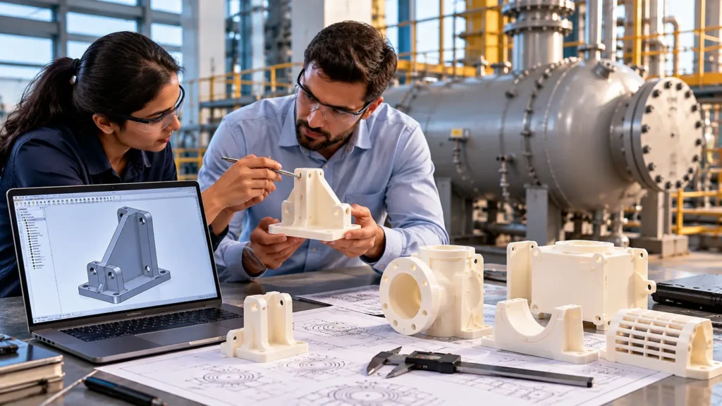
During the development of oil & gas equipment, 3D-printed prototypes can be useful for evaluating non-critical physical aspects such as:
- Equipment component packaging
- Bracket positioning
- Instrument mounting concepts
- Access covers
- Handle locations
- Protective guards
- Cable-routing concepts
- Pipe-support concepts
- Equipment interfaces
- Maintenance access
- Assembly concepts
- Installation tooling
- Fixtures and temporary aids
For example, consider an equipment package containing several instruments, brackets, valves, and protective components.
A CAD assembly may establish that all components fit within the available envelope. A scaled or full-size prototype of selected components can then help the engineering team understand physical accessibility and interaction between components.
For actual oil & gas equipment development, the design still needs to be evaluated against the applicable project specifications, codes, standards, material requirements, calculations, inspection requirements, and manufacturing processes.
Immersiv Techsphere’s oil & gas equipment design workflow covers the progression from 3D modeling through manufacturing-oriented engineering documentation. 3D printing can complement this workflow at the appropriate prototype-validation stage.
3D Printing Does Not Replace FEA or Engineering Calculations
This distinction is important.
A physical prototype can answer some questions that are difficult to answer from a screen, but it cannot independently establish that a component is structurally adequate for its intended service.
For example, a prototype can help determine whether: “Can I physically install this bracket?”
It does not by itself establish: “Can this bracket safely withstand the specified operating load?”
The second question requires appropriate engineering analysis, which may include analytical calculations, FEA, material evaluation, testing, or other applicable validation methods.
For mechanical products and industrial assemblies, FEA and physical prototyping can therefore work together.
The digital workflow may look like:
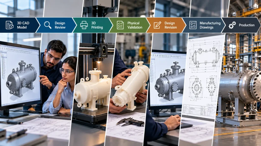
3D CAD Model → Design Review → FEA / Engineering Analysis → 3D Printed Prototype → Fit & Assembly Evaluation → Design Revision → Manufacturing Drawings → Production
Immersiv Techsphere also provides FEA and mechanical design support as part of its engineering capabilities, helping teams evaluate mechanical designs before production.
From CAD Model to 3D Printed Prototype
A reliable prototype-validation workflow starts with the engineering model rather than treating 3D printing as an isolated activity.
Step 1: Develop the 3D CAD Model
The component is first developed using the appropriate CAD platform.
The model should represent the intended geometry, interfaces, mounting features, and relevant design requirements.
Step 2: Perform Digital Design Checks
Before printing, engineers can perform:
- Interference checks
- Clearance checks
- Assembly reviews
- Dimensional reviews
- Motion checks
- Design-for-manufacturing reviews
This prevents obvious CAD issues from being transferred directly into the prototype.
Step 3: Identify What Needs Physical Validation
Not every component needs to be printed.
Engineers should identify the features where physical evaluation adds value.
For example:
- Complex interfaces
- Ergonomic features
- Assembly access
- Installation sequence
- Clearance around equipment
- Mounting arrangements
Step 4: Select the Prototype Material and Process
The material and additive manufacturing process should be selected according to the validation objective.
A prototype intended only for visual and dimensional evaluation may have different requirements from one intended for limited functional testing.
This distinction is important because additive manufacturing processes can produce different dimensional, mechanical, thermal, and surface characteristics. NIST highlights the importance of material characterization, process monitoring, dimensional measurement, and part qualification in additive manufacturing.
Step 5: Print and Inspect
After printing, the prototype should be inspected against the intended geometry.
Depending on the requirement, engineers may check:
- Overall dimensions
- Hole locations
- Interface geometry
- Fit
- Assembly
- Surface condition
- Critical features
Step 6: Feed Findings Back Into CAD
The most valuable part of prototyping is not the printed component itself; it is the engineering feedback generated from it.
If a bracket is difficult to access, the CAD model can be modified.
If a cover interferes with another component, the geometry can be revised.
If an interface requires adjustment, the digital model can be updated before manufacturing.
This creates a controlled design–prototype–review–revision cycle.
How 3D Printing Can Reduce Manufacturing Risk
The primary value of rapid prototyping is not simply producing a part faster.
It is the opportunity to discover certain design problems before they become manufacturing problems.
Consider an equipment component that requires a custom bracket.
Without physical prototyping, the workflow might proceed from:
CAD → Drawing → Fabrication → Assembly
If the bracket interferes with another component during assembly, the issue may only become apparent after fabrication.
With an appropriate prototype stage:
CAD → Prototype → Physical Review → CAD Revision → Drawing → Fabrication
the design team has an additional opportunity to identify and correct the issue before production.
This can be particularly useful when manufacturing involves expensive materials, specialized fabrication, machining, welding, or complex assembly.
NIST describes rapid design iteration as one of the potential benefits of additive manufacturing, while also emphasizing that AM introduces its own process and qualification considerations.
Important Limitations of 3D-Printed Prototypes
3D printing should not be treated as a universal substitute for production validation.
Engineers need to consider:
- Material Differences: The prototype material may differ substantially from the final production material. A polymer prototype, for example, cannot automatically represent the mechanical or thermal behavior of a metal production component.
- Manufacturing Process Differences: A 3D-printed component may have characteristics that differ from a machined, forged, cast, or fabricated component.
- Dimensional Accuracy: The achievable dimensional accuracy depends on the additive manufacturing technology, machine, material, geometry, orientation, process parameters, and post-processing.
- Anisotropy and Internal Defects: Some additive manufacturing processes can produce direction-dependent properties and internal imperfections. NIST identifies anisotropic properties and internal defects among the challenges involved in qualification and measurement of AM parts.
- Regulatory and Code Requirements: For oil & gas equipment, a prototype does not replace required engineering calculations, inspection, testing, certification, or compliance activities.
ASME Y14.46 specifically addresses product definition considerations for additive manufacturing, reflecting the need to communicate AM-specific design information clearly.
3D Printing as Part of a Modern Mechanical Engineering Workflow
The strongest approach is not to view 3D printing as a replacement for conventional engineering methods.
Instead, it can become one step within a broader digital engineering workflow:
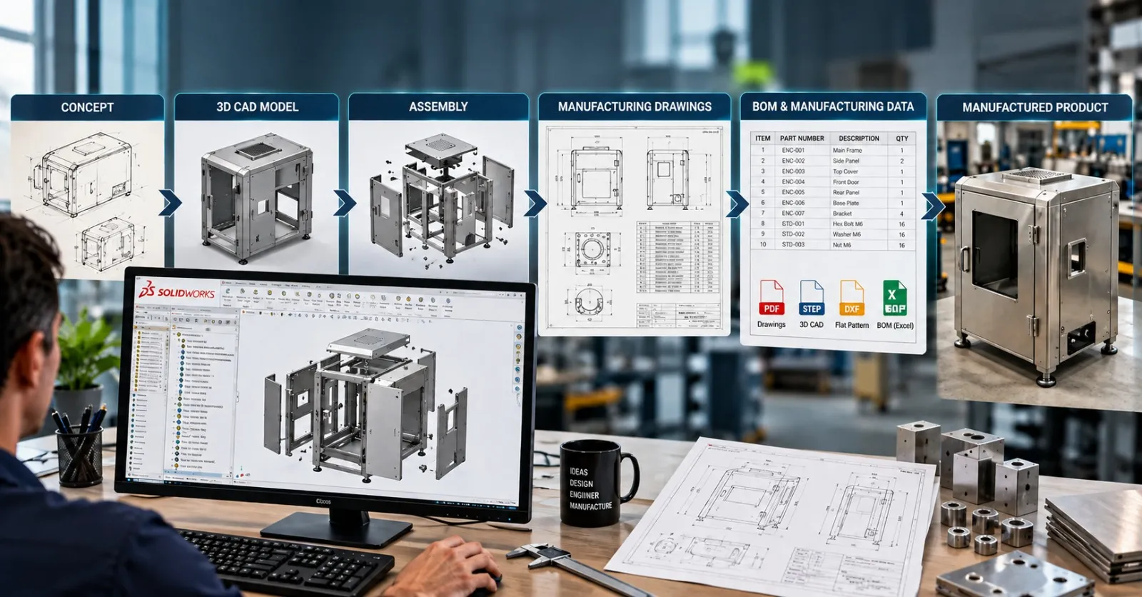
Concept → 3D CAD Design → Digital Design Review → Simulation / FEA Where Required → 3D Printed Prototype → Physical Validation → Design Revision → Manufacturing Drawings → Production
This approach combines digital and physical validation.
CAD provides precise digital geometry.
Simulation can provide engineering insight into defined loading and boundary conditions.
3D printing provides a physical representation for selected design checks.
Manufacturing drawings communicate the approved design for production.
The result is a more structured path from engineering concept to manufactured equipment.
For teams working with repetitive engineering workflows, this process can also benefit from CAD automation. Automated model configurations, drawing generation, BOM creation, and documentation can help reduce repetitive engineering work while keeping engineers responsible for design decisions and validation.
FAQs
Yes. 3D printing can help mechanical engineers physically evaluate selected aspects of a design, including fit, interfaces, assembly, accessibility, ergonomics, and geometry, before manufacturing.
They can be useful for selected prototype and design-review applications, particularly for non-critical components, interfaces, brackets, access features, fixtures, and packaging studies. A printed prototype should not automatically be considered suitable for pressure, temperature, structural, or hazardous-service applications.
No. 3D printing and FEA address different validation needs. FEA can be used to evaluate defined loading and boundary conditions, while a physical prototype can help evaluate physical fit, assembly, accessibility, and other characteristics.
It can help identify certain physical design issues before production, giving engineers an opportunity to modify the CAD design before committing to manufacturing. The extent of benefit depends on the product, prototype quality, validation objectives, and manufacturing process.
A suitable 3D CAD model must generally be converted into a file format supported by the selected additive manufacturing workflow. The model may also require preparation for the particular printing process, including considerations such as build orientation, supports, tolerances, and manufacturability.
Conclusion
3D printing helps engineers validate product designs before manufacturing by turning digital CAD geometry into physical prototypes that can be inspected, assembled, handled, and reviewed.
For mechanical engineering, its greatest value is often in areas such as fit, interfaces, accessibility, assembly sequence, ergonomics, and complex geometry.
For oil & gas equipment development, 3D printing can be particularly useful for selected non-critical prototype components and physical design reviews. It should, however, be used alongside engineering calculations, simulation, inspection, testing, applicable codes and standards, and production-process validation rather than as a replacement for them.
The broader principle is simple:
Validate what can be validated digitally. Prototype what benefits from physical evaluation. Revise the CAD model before committing to manufacturing.
That combination of 3D CAD, engineering analysis, physical prototyping, and manufacturing documentation can help engineering teams identify design issues earlier and make better-informed decisions before production begins.
Have a Project in Mind?
Need help with 3D animation, industrial visualization, HSE training animation, or product visualization? Tell us about your project and our team will get back to you.