

Table of Contents
SolidWorks and Inventor design automation, 2D to 3D migration, and ERP integration: from quotation to the workshop floor
The Problem: Engineering Hours Are Your Hidden Bottleneck
Most manufacturing MSMEs lose margin before a single part is cut. Engineers rebuild near-identical models for every enquiry. Estimators work from spreadsheets disconnected from the design. BOMs are typed by hand. Drawings are edited one by one. The workshop receives PDFs, then calls the design office to clarify them.
The cause is not a lack of skill. It is a lack of CAD automation. Repetitive design work is being done manually, and every manual step adds delay, error and cost.
This blog covers how CAD customization and design automation in SolidWorks and Inventor fix this, and how they connect with your ERP integration, workflow improvement and shop-floor communication.
What Is CAD Automation and Design Automation?
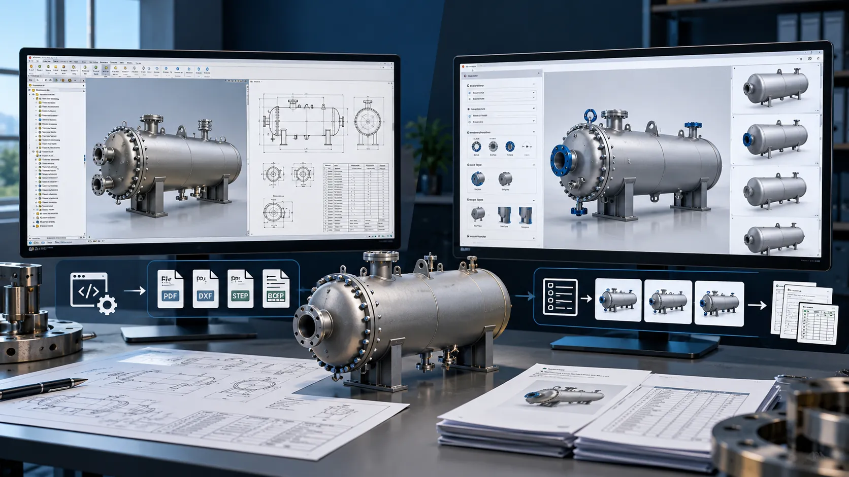
CAD automation uses rules, templates, macros and APIs to generate models, drawings and BOMs from a defined set of inputs, instead of drawing each variant from scratch.
Design automation goes one step further. It captures your engineering logic (sizing rules, standard parts, material selection, manufacturing constraints) and applies it automatically every time a new order arrives.
Typical tools and approaches:
- SolidWorks: DriveWorks, SolidWorks API (VB.NET, C#), design tables, configurations, macros, custom add-ins
- Inventor: iLogic, Inventor API, Frame Generator and parametric templates
- Both: rule-based configurators, CPQ (Configure-Price-Quote) front ends, automated BOM and drawing generation
Manufacturers can implement CAD automation solutions using SolidWorks API, VBA macros, custom add-ins and rule-based design systems to automate repetitive modelling, drawing generation, BOM creation and engineering documentation.
Where MSMEs Gain the Most
1. Faster Estimation and Quotation
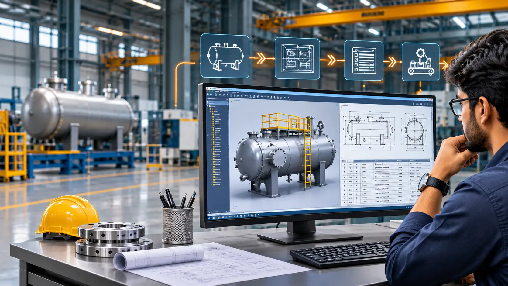
When an enquiry arrives, the input form (dimensions, capacity, material, options) drives a configured 3D model. Weight, cut length, surface area and component count come straight from the model, not from a guess.
- Quotation turnaround drops from days to hours
- Cost estimates are based on real geometry and BOM data
- Sales can quote without waiting for the design team
- Win rate improves because you respond first
For manufacturers handling multiple product variants, Configurator and CPQ solutions can connect product selection, engineering rules, automated BOM generation and pricing logic to streamline quotation workflows and reduce manual engineering involvement.
2. Automated BOM Generation
A manual BOM is the most common source of procurement and production errors. With design automation, the BOM is generated from the model itself:
- Correct part numbers, quantities, materials and finishes
- Standard and bought-out items pulled from a controlled library
- Multi-level BOMs structured to match how you actually build
- Revision changes flow through automatically
3. Production Drawings Without Manual Drafting
Automated drawings are created in your company standard: title block, views, dimensions, GD&T notes, balloons, BOM tables, weld symbols and revision data.
- Drawing time per project drops significantly
- Every drawing follows one standard, regardless of who designed the job
- Fewer shop-floor queries caused by missing or inconsistent information
- Faster release to production
4. Reduced Rework and Errors
Rules enforce limits at the design stage. A shaft that violates a minimum diameter or a plate that fails a thickness rule is flagged before it reaches the workshop, not after the material is cut.
2D to 3D Migration: The Foundation
Automation depends on a 3D parametric model. If your drawings still live in 2D, migration is the first step.
Why 2D Workflows Hold MSMEs Back
- Every variant means redrawing or editing multiple views by hand
- No automatic BOM, mass properties or interference checks
- Design intent lives in the draftsman’s head, not in the file
- Hard to automate, hard to hand over, hard to scale
A Practical Migration Path
- Audit: List your top-selling products and most repeated designs. Start with the 20% that generates 80% of the work.
- Standardize: Define part libraries, naming conventions, materials and drawing templates.
- Model: Rebuild legacy 2D drawings as parametric 3D models in SolidWorks or Inventor, with intent built in (configurations, iLogic parameters, design tables).
- Automate: Add rules, configurators and drawing automation on top of the 3D master model.
- Integrate: Connect the output to your ERP and production planning.
- Train: Upskill the team so the system stays in use and is maintained in-house.
Result: a one-time migration investment that converts every future order into a repeatable, faster process.
ERP Integration: Closing the Loop
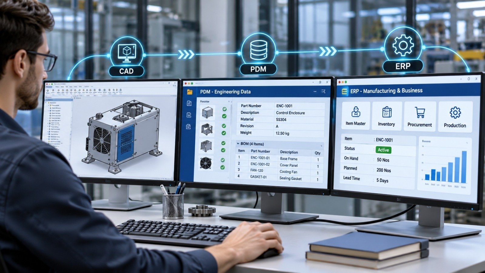
CAD automation delivers its full value only when design data reaches the rest of the business. ERP integration removes re-entry between engineering and operations.
What can flow automatically from CAD to ERP:
- Item masters and part numbers
- Multi-level BOMs with quantities, materials and units
- Revision and engineering change data
- Routing and process information
- Weight, dimensions and cost-driving attributes
Benefits:
- No double entry: The BOM released from CAD is the BOM purchasing and production see
- Accurate procurement: Purchase orders are based on current revisions, not outdated files
- Better costing: Actual BOM data feeds into job costing and margin analysis
- Traceability: Every order is linked to a design revision
ERP systems such as SAP, Tally Prime, Zoho, Odoo and custom in-house systems can be connected with custom APIs, middleware or structured data exchange, depending on what you already run.
Making the Whole Workflow Immersive and Easy to Understand
A design that only the design office understands is a bottleneck. The goal of workflow improvement is that everyone, from management to the workshop, sees the same information in a form they can use.
For management:
- Visual 3D product configurators for quick review and approval
- Dashboards that connect quotations, BOMs, order status and engineering workload
- Faster, better-informed go/no-go decisions
For sales and customers:
- Interactive 3D visualization of the configured product before an order is confirmed
- Fewer misunderstandings and fewer late changes
For the workshop:
- 3D models, exploded views and assembly sequences alongside drawings
- Clear instructions that reduce interpretation errors
- AR/VR-based assembly and training content for operators, so new staff learn faster
When 3D data is the single source of truth, management, design, procurement and production work from the same model instead of passing around separate files.
Business Impact at a Glance
| Area | Before | After CAD Automation |
|---|---|---|
| Quotation | Manual, days | Configured, hours |
| BOM | Typed manually | Auto-generated from model |
| Drawings | Drafted per job | Auto-generated to standard |
| ERP data | Re-entered | Integrated |
| Errors and rework | Frequent | Rule-checked at design stage |
| Scalability | Needs more engineers | Handles more orders with the same team |
Where to Start
You do not need to automate everything at once. A sensible order:
- Pick one repeatable product line.
- Migrate it from 2D to parametric 3D.
- Automate its model, BOM and drawings.
- Link it to your estimation process and ERP.
- Measure hours saved and errors removed, then extend to the next product.
Conclusion
For manufacturing MSMEs, CAD customization, design automation and ERP integration are not enterprise-only luxuries. They are practical ways to quote faster, cut engineering hours per order, reduce errors and grow without adding headcount. Migrating from 2D to 3D and automating estimation, BOM and production drawings in SolidWorks or Inventor gives every department a shared, visual and reliable view of the product.
Immersiv Techsphere provides CAD automation, SolidWorks and DriveWorks customization, CPQ development, ERP integration and 3D/AR/VR visualization for manufacturers. To discuss automating your workflow, get in touch for a process review.
Frequently Asked Questions
It uses configured 3D models to extract weight, dimensions, material quantities and other costing data directly.
Yes. APIs, macros, DriveWorks and iLogic can automate BOM creation and production drawings using predefined engineering standards.
Parametric 3D models provide the foundation for automated drawings, BOM generation, design configurations and engineering validation.
Yes. CAD data such as BOMs, part numbers, materials and revision details can be transferred to ERP systems through APIs, middleware or structured data exchange.
Automated design rules identify dimensional and design-limit violations before drawings are released for production.
Have a Project in Mind?
Need help with 3D animation, industrial visualization, HSE training animation, or product visualization? Tell us about your project and our team will get back to you.