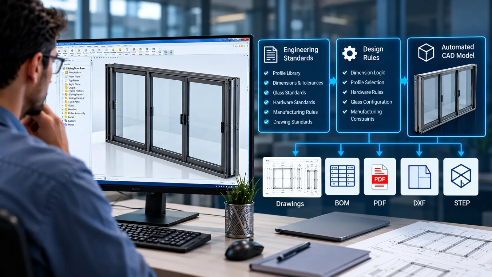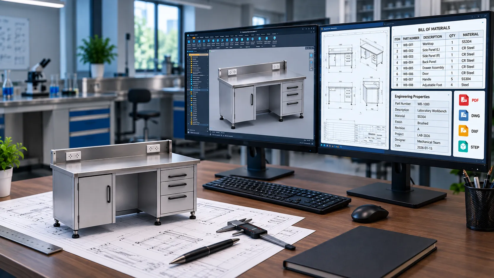

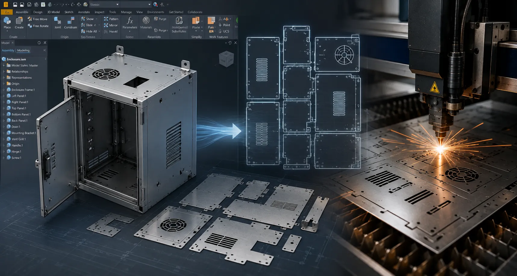

Table of Contents
Introduction
For sheet metal manufacturers, generating CNC-ready data is often one of the most repetitive stages between engineering design and production.
An engineer may need to open individual parts, verify the sheet metal flat pattern, export a DXF, select the correct layer or geometry options, enter a file name, save the file to the right folder, and repeat the process for dozens or hundreds of components.
When product variations increase, this manual process can become a significant engineering bottleneck.
Autodesk Inventor provides a powerful environment for automating this workflow through its Inventor API, iLogic, and .NET-based development capabilities. Instead of manually exporting every flat pattern, an automated workflow can identify sheet metal components, generate or update flat patterns, export DXF files, apply naming rules, and organize manufacturing data consistently.
This article explains how Inventor API automation can streamline DXF export and CNC data generation, what parts of the workflow can be automated, and where it can create the greatest value for manufacturing teams.
What Is DXF Export Automation in Autodesk Inventor?
DXF export automation is the process of using software rules, APIs, or scripts to automatically generate DXF files from CAD models without requiring engineers to perform every export manually.
In a typical sheet metal workflow, the CAD model contains:
- Part geometry
- Sheet metal thickness
- Bend information
- Material information
- Flat pattern
- Manufacturing parameters
- Part number or custom properties
An automated process can read this information from Autodesk Inventor and use it to generate manufacturing-ready DXF files according to predefined rules.
For example:
Inventor Sheet Metal Model → Flat Pattern → DXF Export → File Naming → Manufacturing Folder → CNC Workflow
Instead of manually repeating these steps for every part, the Inventor API can execute them systematically.
Why Manual DXF Export Becomes a Problem
Manual DXF generation may appear simple when working with a few parts. The challenge becomes much larger when engineering teams handle high-volume or configurable products.
1. Repetitive Export Operations
A typical workflow may require engineers to:
- Step 1: Open a part.
- Step 2: Activate the flat pattern.
- Step 3: Check the model.
- Step 4: Select DXF export.
- Step 5: Configure export options.
- Step 6: Choose a location.
- Step 7: Enter the file name.
- Step 8: Repeat the process.
For hundreds of sheet metal components, these actions consume considerable engineering time.
2. Inconsistent File Naming
Manufacturing workflows depend heavily on accurate file identification.
Manual exports can result in:
- Incorrect file names
- Duplicate names
- Missing revision information
- Inconsistent part numbers
- Files saved in the wrong folder
Automation can derive file names directly from Inventor properties such as:
- Part number
- Description
- Revision
- Material
- Thickness
- Configuration
3. Incorrect Export Settings
DXF files may need specific export settings depending on the downstream manufacturing process.
An organization may have defined requirements for:
- Units
- Geometry layers
- Bend lines
- Sketch geometry
- Construction geometry
- Line types
- Version compatibility
When engineers manually configure these settings, variation can occur.
4. Difficulty Processing Large Assemblies
A large assembly may contain dozens or hundreds of sheet metal components.
Opening each part individually and exporting DXFs becomes inefficient.
An automated process can identify relevant sheet metal components and process them as a batch.
How Inventor API Automates DXF Export
The Inventor API provides programmatic access to Autodesk Inventor’s models, assemblies, parameters, properties, drawings, and manufacturing-related operations.
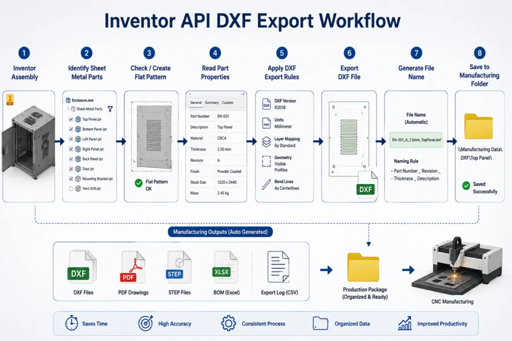
For DXF automation, the workflow can be designed around a sequence of engineering rules.
Step 1: Select the Source Assembly
The automation begins with an Inventor assembly or a selected set of components.
The application can inspect the assembly structure and identify individual part files.
Step 2: Identify Sheet Metal Components
The automation determines which components require flat-pattern DXF output.
For example:
- Sheet metal parts → DXF required
- Purchased components → DXF not required
- Standard hardware → DXF not required
- Machined parts → STEP or other manufacturing output
- Weldments → drawing or fabrication output
This prevents unnecessary files from being generated.
Step 3: Check or Create the Flat Pattern
A sheet metal part must have a valid flat pattern before its unfolded geometry can be exported.
The automation can check whether a flat pattern exists and, where appropriate, create or update it according to the defined workflow.
Step 4: Read Part Information
The Inventor API can retrieve information from the model, including:
- Part Number
- Description
- Material
- Thickness
- Revision
- Custom Properties
- File Path
This information can drive the export process.
Step 5: Generate the DXF
The automation then exports the flat pattern to DXF using predefined settings.
The process can standardize:
- DXF format
- Units
- Layer mapping
- Bend representation
- Geometry selection
- Output location
Step 6: Apply File Naming Rules
Instead of relying on manual naming, the system can construct the file name automatically.
For example: PartNumber_Revision_Thickness.dxf
Or: CustomerCode_PartNumber_Revision.dxf
The exact naming convention depends on the manufacturer’s production workflow.
Step 7: Organize Manufacturing Data
The automation can automatically create or select the appropriate output directories.
For example:
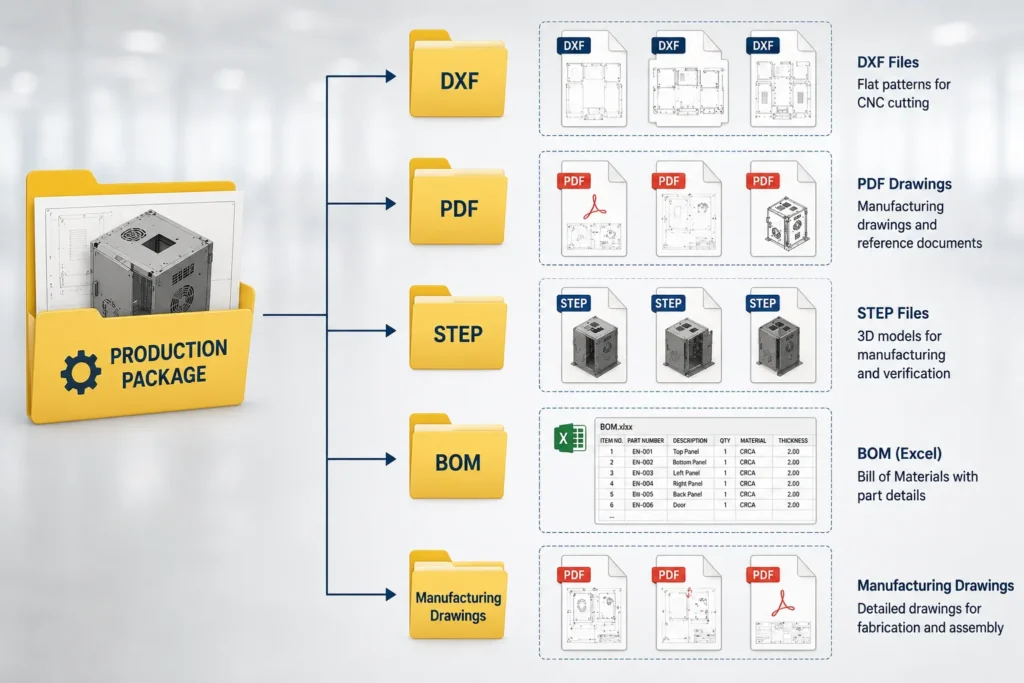
This creates a more structured transition from engineering to manufacturing.
DXF Export Workflow Using Inventor API
A typical automated workflow can be represented as:
Inventor Assembly
↓
Identify Sheet Metal Parts
↓
Check Flat Pattern
↓
Read Part Properties
↓
Apply DXF Rules
↓
Export DXF
↓
Generate Standard File Name
↓
Save to Manufacturing Folder
↓
Update Production Data
The important concept is that DXF generation becomes part of the engineering workflow rather than a separate manual activity.
What CNC Data Can Be Generated Alongside DXF Files?
DXF export is often only one component of a larger manufacturing data workflow.
Depending on the manufacturing process and downstream systems, automation can prepare additional information such as:
- DXF Files: Used for processes such as laser cutting, plasma cutting, waterjet cutting, and CNC sheet processing.
- PDF Drawings: Production teams may require dimensioned drawings containing overall dimensions, bend information, material, thickness, part number, revision, and manufacturing notes.
- STEP Files: For appropriate parts and workflows, STEP files can support CNC machining, supplier communication, external manufacturing, and engineering collaboration.
- BOM Data: Assembly information can be extracted into part numbers, quantities, materials, descriptions, and revision information.
- Manufacturing Metadata: Custom properties can also be exported for downstream systems such as ERP, MES, production planning, procurement, and inventory systems.
This creates a broader CAD-to-manufacturing automation workflow.
Automating DXF Export for Multiple Parts
One of the strongest applications of Autodesk Inventor Automation is batch processing.
Consider a product assembly containing 150 sheet metal components.
A manual workflow could require the engineer to process each component separately.
An automated workflow can instead:
- Read the assembly.
- Identify sheet metal components.
- Check each flat pattern.
- Retrieve part information.
- Apply standard DXF settings.
- Export each DXF.
- Generate standardized names.
- Save the files to the required location.
- Create a processing log.
This approach is particularly useful for manufacturers producing:
- Electrical enclosures
- Control panels
- Industrial cabinets
- Machine guards
- Sheet metal furniture
- Server racks
- Laboratory furniture
- Fabricated equipment
- Industrial machinery
Example: Sheet Metal Cabinet Manufacturing
Consider a configurable sheet metal cabinet.
A customer changes:
- Width
- Height
- Depth
- Number of shelves
- Door configuration
- Material
- Thickness
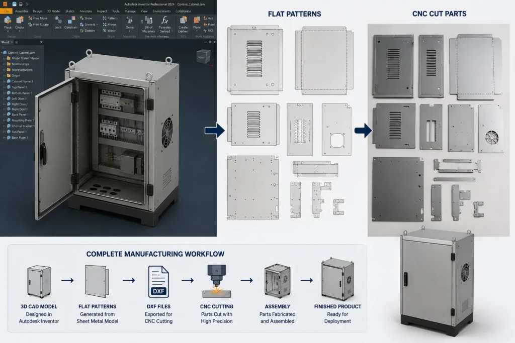
The CAD model may automatically update based on these parameters.
However, the manufacturing workflow still requires new files.
Without automation, engineers may need to:
- Update the model
- Check the flat patterns
- Export multiple DXFs
- Rename files
- Update drawings
- Update BOM information
- Prepare the production folder
With an Inventor API workflow, the same parameter change can trigger a standardized production-data generation process.
The conceptual workflow becomes:
Customer Parameters
↓
Inventor Model Updates
↓
Assembly Regeneration
↓
Sheet Metal Components Identified
↓
Flat Patterns Updated
↓
DXFs Generated
↓
Drawings Generated
↓
BOM Updated
↓
Production Package Created
This is where CAD automation moves beyond simply “exporting a DXF” and becomes part of engineering process automation.
Inventor API vs Manual DXF Export
| Feature | Manual DXF Export | Inventor API Automation |
|---|---|---|
| Single-part export | Manual | Automated |
| Batch DXF generation | Limited | Automated |
| File naming | User dependent | Rule-based |
| Folder organization | Manual | Automated |
| Flat pattern validation | Manual | Rule-based |
| Export settings | User dependent | Standardized |
| Part property extraction | Manual | Automated |
| BOM integration | Separate process | Can be integrated |
| CNC data workflow | Multiple manual steps | Connected workflow |
| Scalability | Limited | High |
| Process consistency | Depends on engineer | Consistent |
The objective is not simply to remove engineers from the process. Instead, Inventor API automation handles predictable, repetitive operations while engineers retain control over design decisions and manufacturing validation.
What Can Be Automated Beyond DXF Export?
A well-designed Autodesk Inventor automation solution can extend considerably beyond DXF generation.
CAD Model Automation
- Parameter updates
- Part generation
- Assembly generation
- Configuration management
- Component replacement
Drawing Automation
- Drawing creation
- Drawing template selection
- View generation
- Dimension placement workflows
- PDF export
Manufacturing Data
- DXF generation
- STEP export
- BOM extraction
- Cut-list information
- Production documentation
File Management
- Automated naming
- Folder creation
- Revision handling
- Output organization
- Duplicate checking
Business-System Integration
Automation can also connect CAD data with:
- ERP systems
- MES platforms
- PDM systems
- Excel-based production systems
- Custom manufacturing databases
This allows engineering information to move more reliably between design and production.
When Should Manufacturers Automate DXF Export?
DXF automation becomes particularly valuable when a company:
- Produces large numbers of sheet metal components
- Manufactures configurable products
- Generates similar DXFs repeatedly
- Uses standardized naming conventions
- Has multiple engineers exporting manufacturing files
- Experiences frequent file-management errors
- Needs faster production-data preparation
- Uses Autodesk Inventor as a primary CAD platform
- Wants to connect CAD with ERP or manufacturing systems
A simple rule is: if engineers repeatedly perform the same export sequence, that sequence is a potential candidate for automation.
The greater the volume and consistency of the workflow, the stronger the case for automation.
Designing a Reliable Inventor API Automation Workflow
Successful automation requires more than writing a script that clicks an export command.
The engineering logic behind the process is equally important.
1. Define Manufacturing Rules
Before development begins, establish:
- Which parts require DXF
- Which layers should be exported
- Required DXF version
- Naming convention
- Folder structure
- Revision rules
- Material and thickness requirements
2. Validate the Source Model
Automation should identify problems before creating production data.
Potential validation checks include:
- Missing flat pattern
- Missing part number
- Missing material
- Invalid thickness
- Missing revision
- Duplicate file names
3. Separate Engineering and Manufacturing Logic
The CAD model should remain responsible for design intent, while the automation layer manages the repeatable manufacturing-data workflow.
This separation makes the system easier to maintain.
4. Add Error Handling
A robust system should not silently fail.
Instead, it should report issues such as:
Part 10245 – DXF Generated
Part 10246 – DXF Generated
Part 10247 – Missing Flat Pattern
Part 10248 – Missing Part Number
Part 10249 – DXF Generated
This gives engineers a clear exception list to review.
5. Maintain an Audit Trail
For production environments, logging can help track:
- Source model
- Revision
- Export date
- Generated files
- Failed exports
- Processing status
This becomes increasingly important as automation expands across engineering and manufacturing.
Benefits of Autodesk Inventor DXF Automation
- Reduced Repetitive Engineering Work: Engineers spend less time performing repetitive export operations.
- Faster Manufacturing Data Preparation: Large batches of DXFs can be processed through a standardized workflow.
- Improved File Consistency: Naming, folders, and export settings follow predefined rules.
- Reduced Documentation Errors: Automation reduces manual interaction with repetitive data-entry and export steps.
- Better Engineering Scalability: Teams can handle higher volumes without increasing manual export work proportionally.
- Stronger CAD-to-CNC Workflow: The connection between the digital product model and manufacturing data becomes more structured.
- Easier Integration: DXF generation can become one stage in a larger workflow involving BOMs, PDFs, STEP files, ERP data, and production documentation.
How Immersiv Techsphere Approaches CAD Automation
At Immersiv Techsphere, CAD automation is approached as an engineering workflow problem rather than simply a scripting task.
Our CAD automation capabilities include:
- Autodesk Inventor automation
- Inventor API development
- SolidWorks API development
- VBA and .NET automation
- Automated DXF generation
- Batch PDF and STEP export
- Drawing automation
- BOM automation
- Custom property extraction
- Manufacturing data generation
- Engineering workflow automation
- ERP-ready data extraction
- Rule-based product automation
For manufacturers using Autodesk Inventor, automation can be developed around the company’s existing models, engineering rules, file structures, and manufacturing requirements.
The objective is to connect design intent → engineering documentation → manufacturing data while reducing repetitive manual operations.
Frequently Asked Questions
Inventor API is the application programming interface provided for Autodesk Inventor that allows developers to interact programmatically with CAD models, assemblies, drawings, parameters, properties, and other Inventor functionality.
Yes. Autodesk Inventor can be integrated with automation workflows that generate DXF files from sheet metal flat patterns. The exact implementation depends on the required export settings and manufacturing workflow.
Yes. A custom Inventor API application can inspect an assembly, identify relevant sheet metal components, process their flat patterns, and generate DXF files according to predefined rules.
Yes. File names can be generated from Inventor properties such as part number, description, revision, material, or other custom properties.
DXF files can serve as manufacturing inputs for processes such as laser cutting, plasma cutting, and other CNC sheet processing workflows. Additional CNC or machine-specific data may require downstream software or post-processing depending on the equipment and manufacturing process.
Yes. A broader automation workflow can combine DXF generation with drawing PDF export, BOM extraction, STEP generation, file naming, and production-package creation.
No. CAD automation is most effective when it handles repetitive, rule-based operations. Engineers remain responsible for design intent, engineering judgment, validation, and exceptions.
Conclusion
DXF generation may be a small step in the overall manufacturing process, but repeated manual exports can create significant engineering overhead when production volumes increase.
Autodesk Inventor and the Inventor API provide a foundation for transforming this repetitive task into a structured automation workflow.
Instead of manually exporting individual flat patterns, engineers can build workflows that:
Identify → Validate → Flatten → Export → Name → Organize → Deliver
The same automation approach can then expand into drawing generation, BOM extraction, STEP export, production documentation, and ERP-ready data.
For manufacturers producing sheet metal products or configurable equipment, the real opportunity is not simply faster DXF export. It is creating a more connected CAD-to-manufacturing workflow where engineering data moves consistently from the Inventor model toward production.
Have a Project in Mind?
Need help with 3D animation, industrial visualization, HSE training animation, or product visualization? Tell us about your project and our team will get back to you.