

Table of Contents
Introduction
Finite Element Analysis (FEA) is widely used to predict how products and structures behave under real-world loading conditions. But a finer mesh does not automatically mean a more accurate simulation.
Mesh quality and mesh selection can significantly influence stress results, deformation, convergence, and computational cost. A mesh that is too coarse may fail to capture important stress concentrations or geometric details, while an unnecessarily fine or poorly shaped mesh can increase computational cost without providing meaningful improvements in accuracy.
For applications such as fixture design, structural analysis, sheet-metal components, and fitness or gym equipment, selecting the right element type, mesh size, and refinement strategy is therefore an important part of the FEA workflow.
- A finer mesh does not automatically produce a more accurate FEA result.
- Element type should match the geometry and physics of the problem.
- Critical regions such as holes, fillets, welds, contacts, and load application areas may require local mesh refinement.
- Mesh quality and mesh size are different considerations.
- Mesh convergence provides evidence that an important engineering result is sufficiently resolved.
- Stress singularities require special interpretation and should not automatically be treated as physical failure conditions.
- Correct loads and boundary conditions are just as important as mesh quality.
- The objective is to achieve a sufficiently accurate and numerically stable solution at a reasonable computational cost.
What Is a FEA Mesh?
In Finite Element Analysis, a physical component is divided into a large number of smaller regions called finite elements. Together, these elements form the computational mesh.
The FEA solver calculates the behavior of these individual elements and assembles their responses to estimate the behavior of the complete component.
Depending on the geometry and analysis requirements, a model may use:
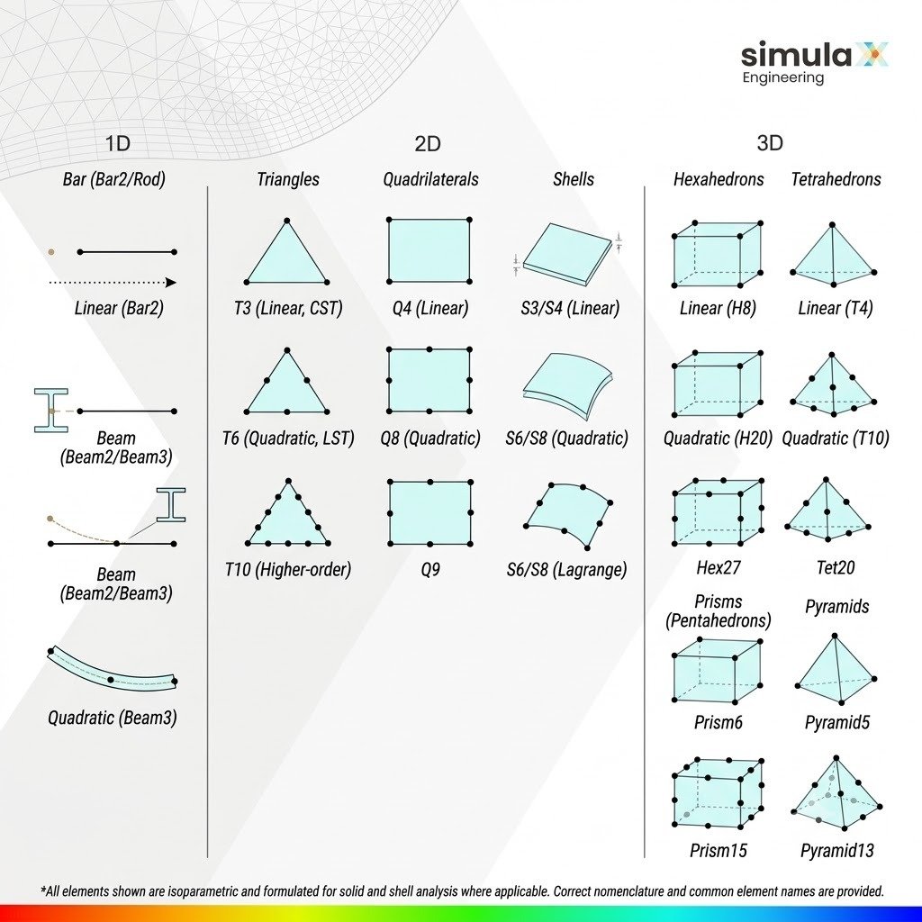
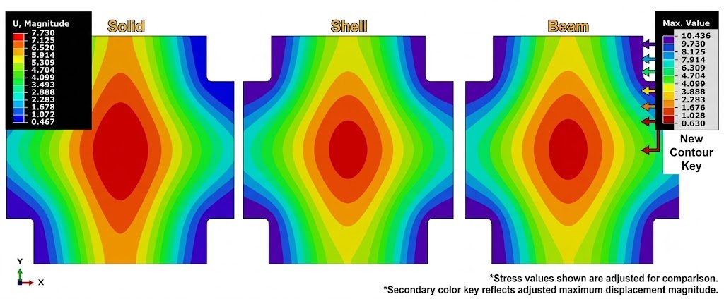
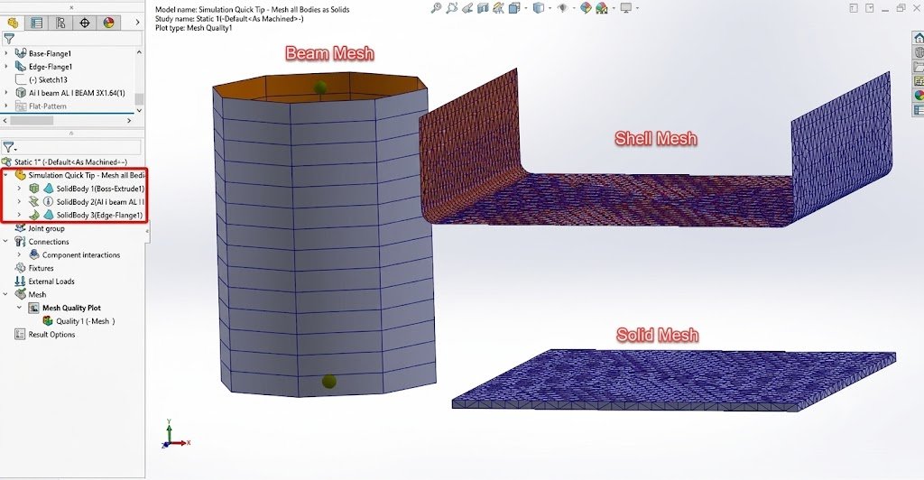
- 1D elements – commonly used for beams, rods, and slender structural members.
- 2D shell elements – useful for thin-walled sheet-metal components and structures.
- 3D solid elements – suitable for components where three-dimensional stress states are important.
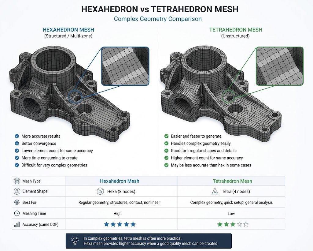
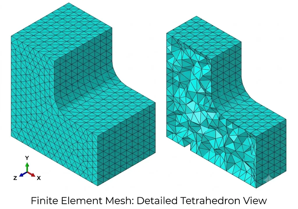
- Tetrahedral elements – flexible for complex 3D geometries.
- Hexahedral elements – often capable of providing efficient and accurate solutions when high-quality hex meshes can be generated.
- Quadratic elements – elements with midside nodes that can better represent curved geometry and deformation than linear elements in many situations.
The goal of meshing is not simply to create the smallest possible elements. Instead, the objective is to create a mesh that represents the important geometry and physical behavior of the component while maintaining acceptable computational cost.
Why Does Mesh Quality Matter in FEA?
FEA is a numerical approximation of a continuous physical system. The mesh determines how effectively the numerical model represents the geometry, deformation behavior, and stress distribution of the component.
Poor mesh selection can lead to:
- Inaccurate stress predictions
- Inaccurate deformation results
- Missed stress concentrations
- Poor representation of curved surfaces
- Numerical problems
- Excessive solver time
- Unnecessary memory consumption
- Difficulty achieving convergence
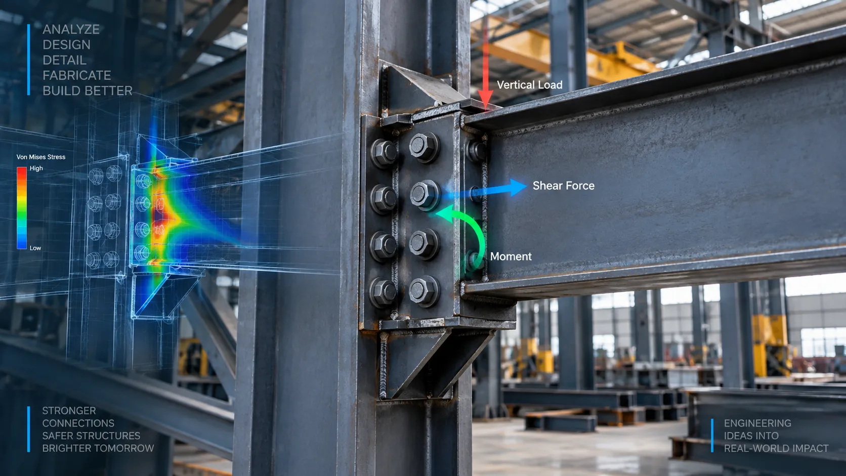
Mesh quality is particularly important when the model contains holes, fillets, sharp geometric transitions, contact regions, welded connections, mounting points, thin sections, brackets, notches, and load application areas.
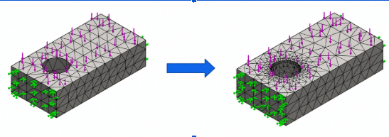
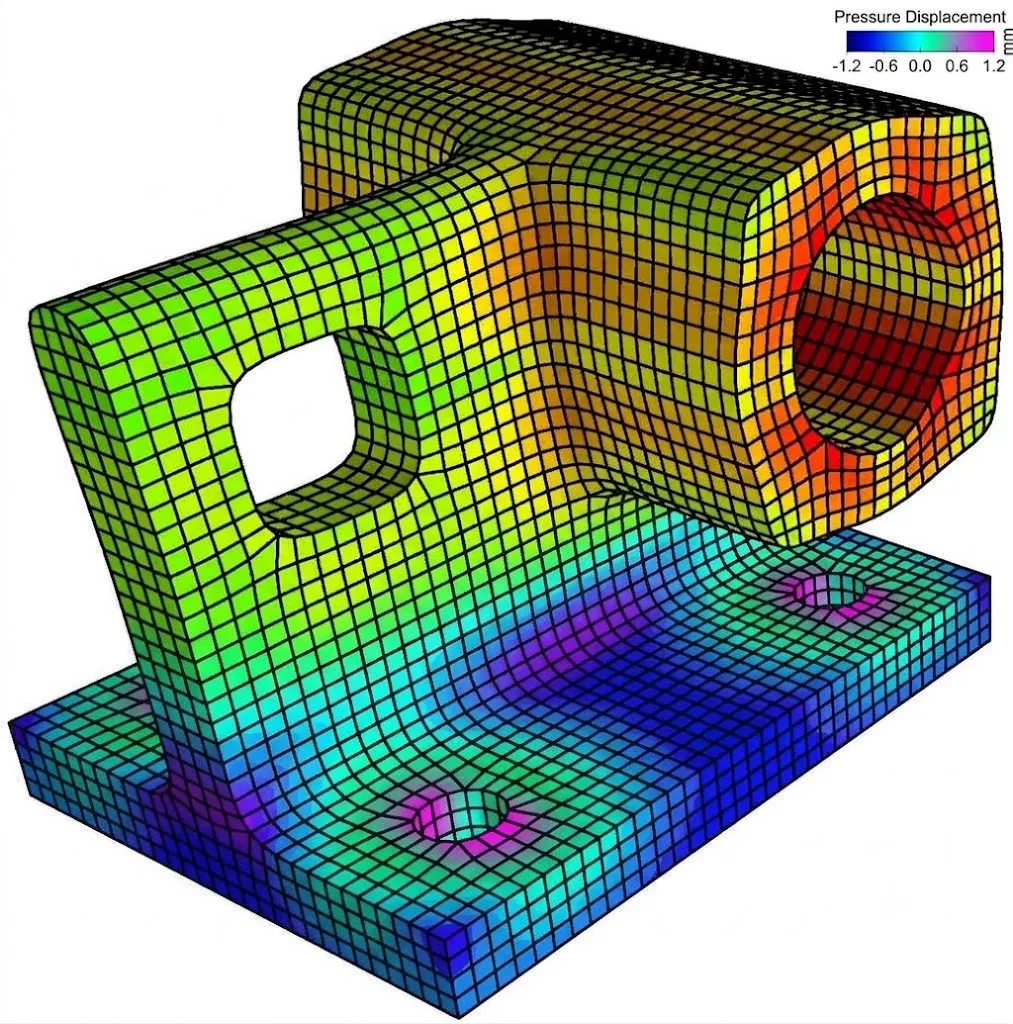
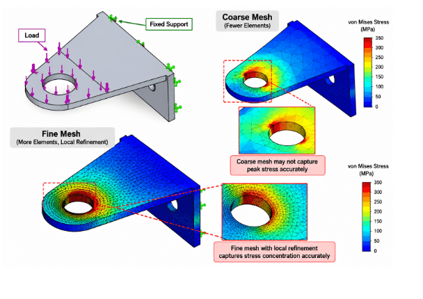
For example, consider a steel fixture with a mounting hole. If the mesh around the hole is too coarse, the solver may not adequately capture the stress gradient around the hole. Refining the mesh in this region can provide a more representative result.
Mesh Size vs. Mesh Quality
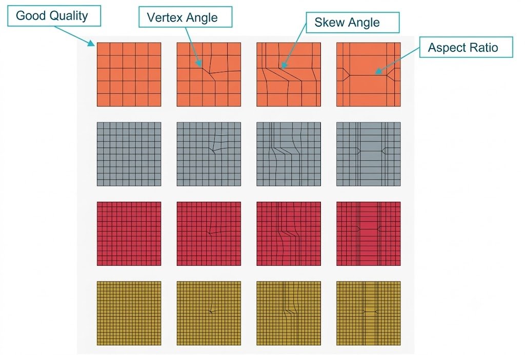
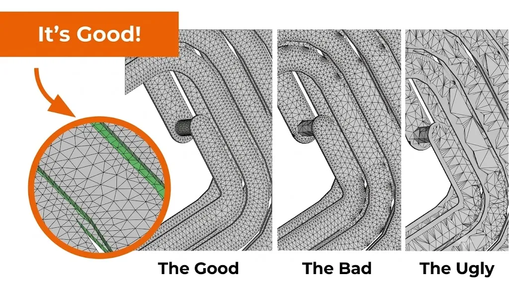
Mesh size primarily controls the level of geometric and solution-field resolution, while mesh quality describes whether the individual elements have suitable shapes and proportions for reliable numerical analysis. A smaller element size does not automatically produce a better solution. For example, a highly distorted 5 mm tetrahedral mesh may provide less reliable numerical behavior than a well-shaped 8 mm mesh in a region where that level of resolution is sufficient.
1. Element Distortion
Elements should not become excessively stretched, compressed, or distorted. Highly distorted elements can reduce solution quality and may cause convergence problems.
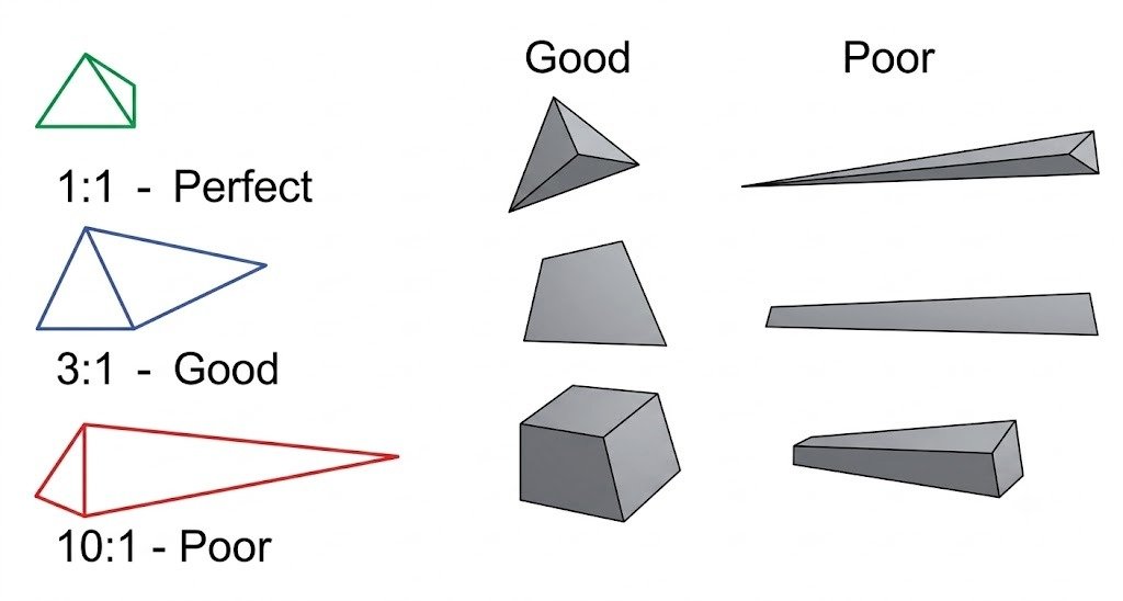
2. Aspect Ratio
Aspect ratio compares characteristic dimensions of an element. Extremely elongated elements can be undesirable in regions where stress or deformation changes significantly in multiple directions.
3. Skewness
Skewness describes how far an element deviates from its ideal geometric shape. Excessive skewness can negatively affect numerical accuracy.
4. Warpage
Warpage is particularly relevant to shell elements. Excessively warped elements may reduce the quality of the shell representation.
5. Jacobian / Element Mapping Quality
The Jacobian is used to evaluate the mapping between an element’s local coordinate system and its physical geometry. Poor Jacobian quality can indicate severely distorted elements.
Mesh-quality criteria should always be evaluated according to the element formulation, solver, and analysis type. There is no single universal numerical limit that applies to every FEA model.
How Mesh Selection Affects FEA Accuracy
Mesh selection influences FEA accuracy in several important ways.
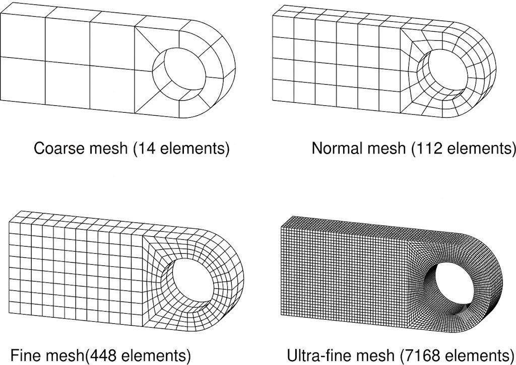
1. Coarse Meshes Can Miss Stress Concentrations
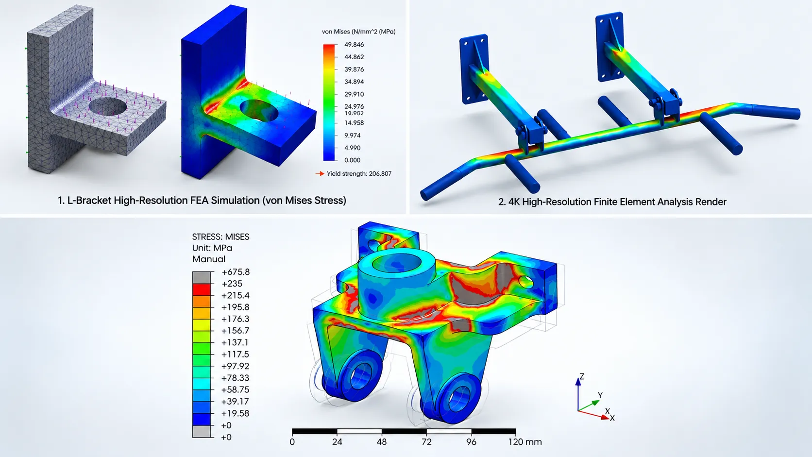
Stress is not distributed uniformly around many geometric features. Holes, fillets, keyways, sharp corners, weld toes, brackets, and bolt locations can produce steep stress gradients.
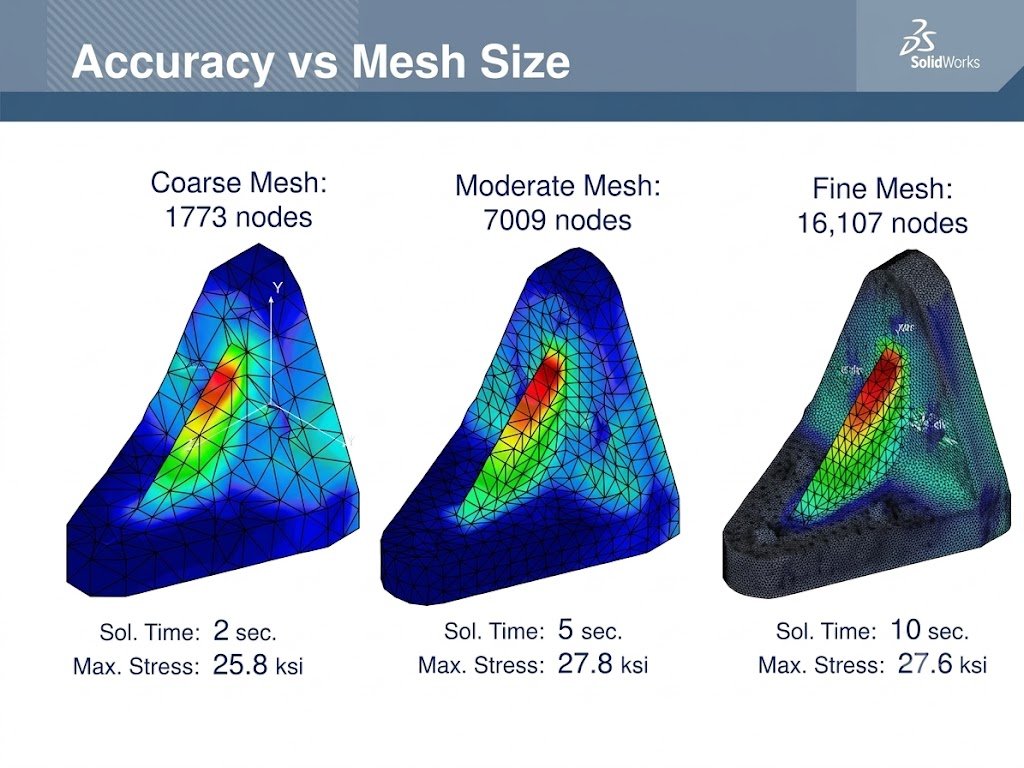
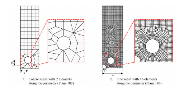
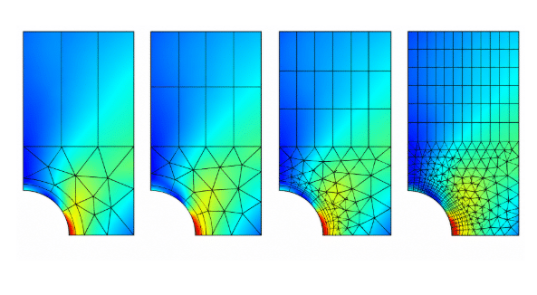
A coarse mesh may smooth these gradients and produce an artificially low peak stress. A local mesh refinement around the feature can better resolve the stress distribution. This is one reason engineers should avoid judging mesh adequacy solely by the total number of elements.
2. Fine Meshes Can Increase Computational Cost
Reducing element size increases the number of elements and degrees of freedom. This can increase solver time, RAM requirements, file size, preprocessing time, and post-processing time.
For large structural assemblies, using a uniformly fine mesh may therefore be inefficient. A more efficient approach is often selective or local refinement: use a reasonable global mesh and apply smaller elements only where the geometry or physics requires additional resolution.
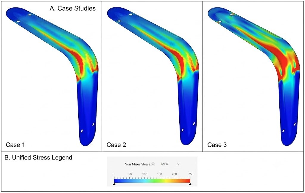
3. Mesh Refinement Can Change the Predicted Stress
| Mesh | Relative Element Size | Maximum Stress | Change |
|---|---|---|---|
| Coarse | Large | 82 MPa | — |
| Medium | Moderate | 94 MPa | +14.6% |
| Fine | Small | 98 MPa | +4.3% |
The decreasing change between successive mesh refinements suggests that the result may be approaching convergence. However, stress convergence should be evaluated at a physically meaningful location and not solely by comparing the absolute maximum stress.
What Is Mesh Convergence?
Mesh convergence is the process of refining the mesh and checking whether important simulation results stabilize.
A typical convergence study involves creating an initial mesh, solving the model, recording a relevant result, refining the mesh, solving again, comparing the results, and repeating until the result changes by an acceptable amount.
The monitored quantity could be displacement, reaction force, strain, stress at a meaningful location, natural frequency, buckling load, or contact pressure.
| Mesh | Maximum Displacement | Change |
|---|---|---|
| Coarse | 1.72 mm | — |
| Medium | 1.79 mm | 4.1% |
| Fine | 1.81 mm | 1.1% |
| Very Fine | 1.82 mm | 0.6% |
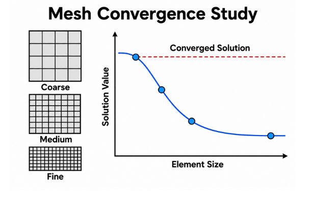
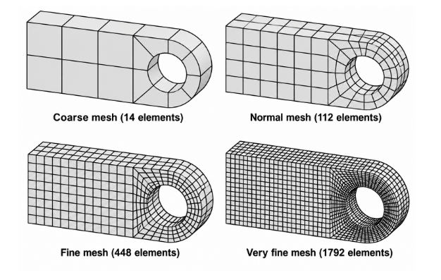
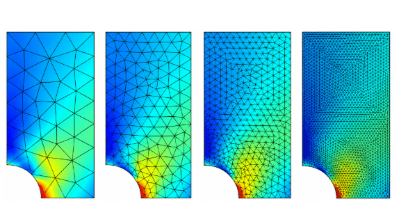
The decreasing percentage change indicates that the displacement result is approaching a stable value. The acceptable convergence criterion depends on the engineering objective and the result being evaluated.
Stress Convergence and Singularities
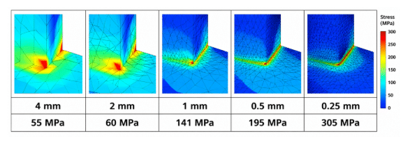
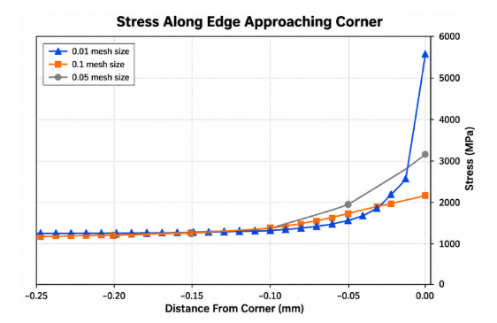
Peak stress at an ideal sharp corner, point load, or other mathematical singularity may not converge to a finite value as the mesh is refined.
If the maximum stress keeps increasing as the mesh becomes finer around a singularity, that does not necessarily mean the model is failing. The issue may be the idealized geometry or loading condition itself.
Engineers may instead evaluate stress away from the singularity, averaged or linearized stress where appropriate, structural/hot-spot stress for relevant applications, or a physically realistic fillet or load introduction.
Choosing the Right FEA Element Type
Mesh selection begins before choosing the element size. The element formulation should match the physics and geometry of the problem.
- 1D Elements for Structural Members: Beam or truss-type elements can be effective for tubular frames, structural members, machine frames, and gym equipment frames when the assumptions behind the formulation are appropriate.
- Shell Elements for Sheet-Metal Structures: Shell elements are particularly useful for thin-walled components such as sheet-metal brackets, equipment enclosures, cabinets, structural panels, and fabricated fixtures.
- Solid Elements for Complex Components: Solid elements are appropriate when the component has significant three-dimensional behavior, including thick brackets, complex castings, machined components, load-bearing joints, complex contact regions, and components where through-thickness stress matters.
Tetrahedral vs. Hexahedral Meshes
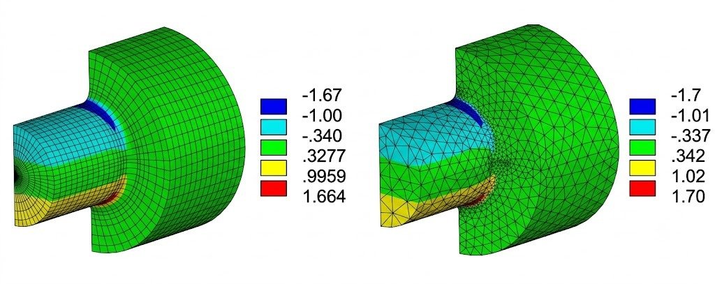
Neither element type is universally better. The appropriate choice depends on geometry, element formulation, mesh quality, solver capabilities, and analysis requirements.
Tetrahedral Elements
- Easier automated meshing
- Good suitability for complex geometries
- Relatively straightforward geometry coverage
Hexahedral Elements
- Efficient representation of certain geometries
- Good accuracy per degree of freedom in appropriate applications
- Suitability for structured or sweepable geometries
Generating a high-quality hexahedral mesh for complex geometry can be significantly more difficult. Therefore, “hex is always better than tet” is not a technically valid general rule.
How to Choose FEA Mesh Size
There is no single mesh size that is appropriate for every FEA model. Mesh size should be selected based on geometry, stress gradients, loading conditions, element formulation, and the engineering objective.
A practical approach is to begin with a reasonable global mesh, identify regions where the geometry or solution changes rapidly, and apply local refinement in those areas. The selected mesh should then be evaluated through mesh convergence or another appropriate verification method.
Important regions may include holes, fillets, welded joints, brackets, contact interfaces, load application points, and abrupt changes in section thickness.
Global Mesh vs. Local Mesh Refinement
Using a fine mesh throughout the entire model is often unnecessary. A more efficient strategy is to use a reasonable global mesh and selectively refine regions where additional resolution is required.
For example, a gym equipment frame may use a relatively coarse mesh across long tubular members while using finer elements around welded brackets, adjustment holes, hinge locations, and load introduction points.
This approach can improve solution resolution in critical areas while controlling computational cost.
Mesh Quality for FEA of Fixtures
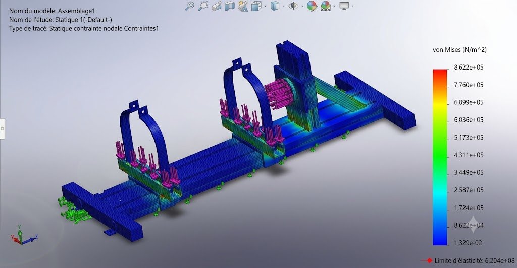
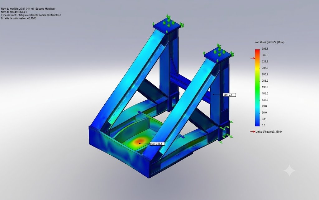
Fixtures are frequently exposed to localized forces, clamping loads, vibration, and repeated operational loads. Examples include welding fixtures, machining fixtures, inspection fixtures, assembly fixtures, test fixtures, and holding devices.
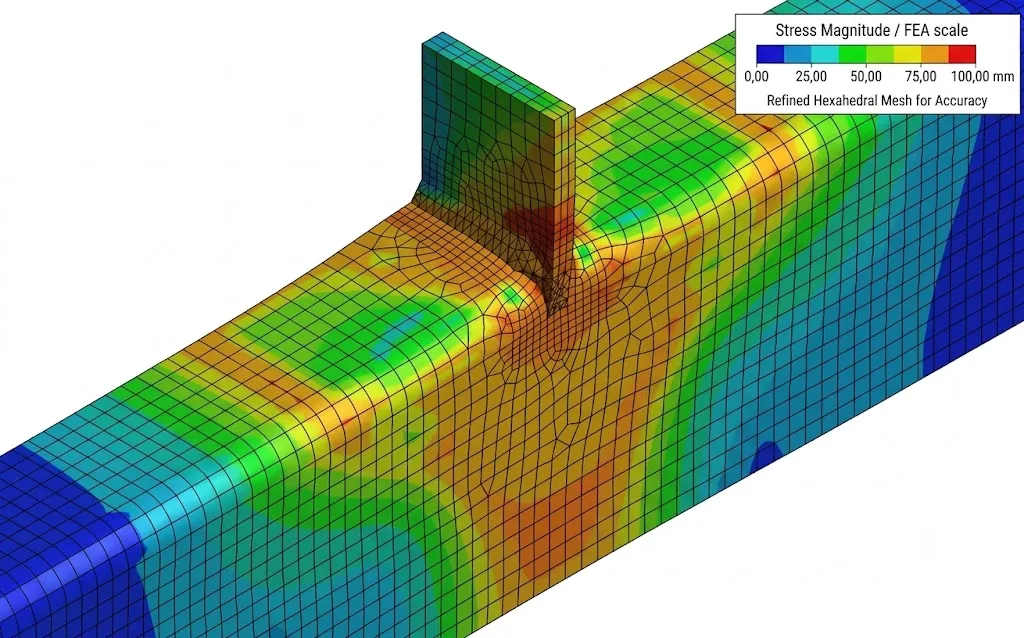
For a fixture supporting a heavy component, important areas for mesh refinement may include mounting holes, clamp locations, welded joints, load introduction points, brackets, transitions between sections, and bolted connections.
A coarse global mesh combined with local refinement can often provide a good balance between accuracy and computational efficiency.
Even an excellent mesh cannot compensate for incorrect boundary conditions. Therefore, mesh quality is only one part of FEA model quality.
Mesh Selection for Structural FEA
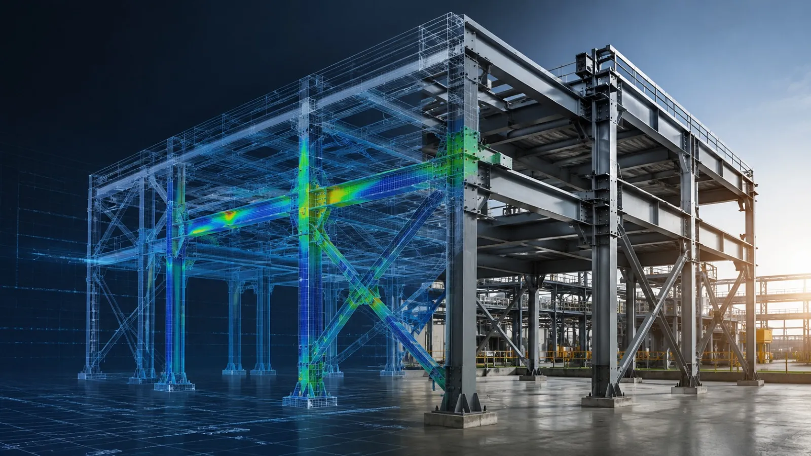
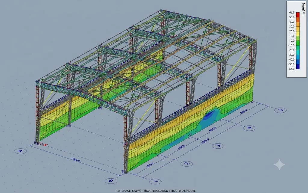
Structural components often contain long members, plates, brackets, and joints. A fabricated steel frame could potentially be modeled using beam elements for slender members, shell elements for plates, and solid elements for critical connection details.
The key is to use the appropriate level of geometric detail for the engineering question being asked. If the goal is to determine overall frame deformation, modeling every weld and bolt thread as a 3D solid may add enormous computational cost without improving the answer. If the goal is to investigate a local connection failure, however, a more detailed model may be justified.
Mesh Selection for Fitness and Gym Equipment
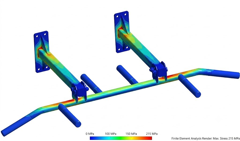
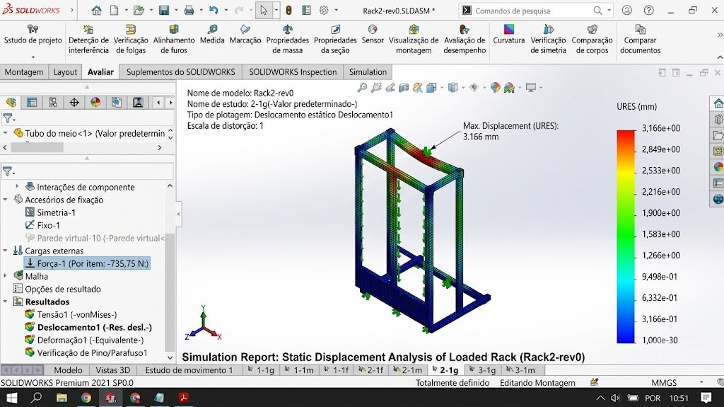
FEA is also valuable for evaluating fitness and gym equipment, where structural integrity, repeated loading, user weight, and dynamic effects can be important.
- Squat racks
- Power racks
- Weight benches
- Cable machines
- Strength-training equipment
- Exercise frames
- Adjustable benches
- Gym storage systems
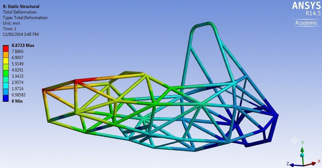
For a gym equipment frame, engineers may initially use beam or shell elements to evaluate overall structural behavior. Critical areas can then be modeled or refined in greater detail.
Static analysis is not always sufficient
Gym equipment can experience static loading, cyclic loading, impact loading, vibration, and fatigue loading. Therefore, a static FEA model should not automatically be interpreted as a complete validation of the equipment. Depending on the application, additional analyses such as fatigue, modal, nonlinear, contact, or dynamic analysis may be required.
Local Mesh Refinement: A Practical Strategy
One of the most effective approaches to mesh optimization is local refinement.
- Create a reasonable global mesh.
- Identify critical regions.
- Apply local mesh controls.
- Re-run the simulation.
- Compare relevant results.
- Perform additional refinement if required.
For example, a gym equipment frame may not need an extremely fine mesh across every tube. However, the region around a welded bracket carrying a concentrated load may require much finer elements. This approach reduces computational cost while improving resolution where it matters.
How Geometry Influences Mesh Requirements
Mesh size should also reflect the smallest geometric features that materially affect the analysis.
- Fillets
- Holes
- Slots
- Bends
- Thickness changes
- Weld regions
- Contact surfaces
- Cutouts
If a small feature is irrelevant to the engineering question, it may sometimes be simplified or suppressed. But removing a feature that controls stress concentration can invalidate the analysis.
Example
Consider a sheet-metal bracket with a mounting hole. If the objective is to determine the overall displacement of the bracket, a relatively coarse mesh may be sufficient away from the hole. If the objective is to estimate stress concentration around that hole, the local region requires considerably better resolution.
Mesh requirements should therefore be driven by the engineering objective, not simply by the level of detail present in the CAD model.
FEA Mesh Quality: What Engineers Should Check
- Geometry
- Are critical geometric features represented?
- Have unnecessary features been simplified?
- Are thin sections modeled appropriately?
- Element Selection
- Is the element formulation appropriate?
- Are shell, beam, or solid elements being used for the right physical assumptions?
- Are linear or quadratic elements appropriate?
- Mesh Quality
- Are there highly distorted elements?
- Are aspect ratios reasonable for the application?
- Is skewness acceptable?
- Is warpage acceptable for shell elements?
- Are there problematic transition regions?
- Refinement
- Are holes and fillets sufficiently resolved?
- Are load introduction areas refined?
- Are contact regions adequately meshed?
- Convergence
- Has mesh refinement been performed?
- Does the relevant engineering result stabilize?
- Are you monitoring a physically meaningful quantity?
- Boundary Conditions
- Do constraints represent the actual physical mounting conditions?
- Are loads applied realistically?
- Are contacts modeled appropriately?
- Results
- Is the result physically reasonable?
- Are unexpected high-stress regions investigated?
- Are stress singularities identified?
- Are results compared against appropriate design criteria?
- Has the model been verified against the engineering objective?
Common FEA Meshing Mistakes
Mistake 1: Assuming a Fine Mesh Is Always More Accurate
More elements can improve resolution, but refinement alone does not fix incorrect material properties, unrealistic constraints, incorrect loads, poor contact definitions, wrong element formulations, or bad geometry assumptions.
Mistake 2: Using the Same Mesh Size Everywhere
Uniform mesh sizing is often inefficient. Critical areas generally deserve more attention than regions with smooth, slowly varying fields.
Mistake 3: Ignoring Stress Singularities
A very high stress at an idealized sharp corner should not automatically be interpreted as a physical failure condition. Investigate whether the result represents a real stress concentration or a mathematical singularity.
Mistake 4: Refining Without Performing Convergence Checks
Changing the mesh without checking how the result changes makes it difficult to establish whether the solution is sufficiently resolved.
Mistake 5: Focusing Only on Element Count
Two meshes with the same number of elements can have very different quality and accuracy. Element distribution, formulation, geometry representation, and refinement location all matter.
Mistake 6: Refining the Mesh Without Checking the Model Setup
Mesh refinement cannot compensate for incorrect loads, boundary conditions, material properties, contacts, or element formulations.
A Practical FEA Mesh Workflow
CAD Model → Geometry Cleanup → Element Selection → Initial Mesh → Quality Check → Solve → Review Results → Local Refinement → Mesh Convergence → Final Validation
The workflow is iterative rather than strictly linear. The objective is not to create the largest possible mesh. It is to establish a numerically stable model that provides sufficiently accurate engineering information at a reasonable computational cost.
How Immersiv Techsphere Can Help With FEA
Immersiv Techsphere combines mechanical engineering, CAD modeling, fixture design, structural design, sheet-metal engineering, and product development to support FEA-driven design decisions.
- FEA model preparation
- Element selection
- Mesh generation and quality assessment
- Local mesh refinement
- Mesh convergence studies
- Structural evaluation
- Design comparison
- Fixture analysis
- Fitness and gym equipment analysis
- Design optimization
Need help evaluating a fixture, structural frame, sheet-metal component, or fitness equipment design? Immersiv Techsphere can support the engineering workflow from CAD preparation and FEA setup through mesh refinement, simulation, and design evaluation.
You can explore Immersiv Techsphere’s capabilities through its mechanical engineering and CAD services.
Frequently Asked Questions About FEA Mesh Quality
FEA mesh quality describes how suitable the finite elements are for numerical analysis. It considers factors such as element distortion, aspect ratio, skewness, warpage, and Jacobian quality, depending on the element formulation and solver.
No. A finer mesh can improve resolution where the solution has high gradients, but it does not automatically make the entire model more accurate.
Mesh convergence is the process of refining a mesh and checking whether a relevant result approaches a stable value.
Neither is universally superior. The correct choice depends on geometry, formulation, mesh quality, and analysis objectives.
Shell elements are often efficient for thin-walled sheet-metal components, but the appropriate formulation depends on thickness, loading, geometry, contacts, and the engineering objective.
There is no universal element size. The mesh should be sufficiently refined to resolve the geometry and stress gradient, with adequacy assessed through convergence or another appropriate verification approach.
Yes. FEA can evaluate static loading, deformation, stress distribution and, in appropriate models, fatigue, modal, contact, nonlinear, or dynamic behavior.
Both matter. Mesh size controls resolution, while mesh quality indicates whether the elements are numerically suitable.
Conclusion
FEA mesh selection directly influences the reliability, resolution, and computational efficiency of a simulation. A coarse mesh can overlook important stress gradients, while excessive refinement can increase computational cost without producing meaningful improvements.
The most reliable approach is to select the appropriate element type, maintain suitable element quality, refine critical regions, avoid unnecessary global refinement, investigate stress singularities, perform mesh-convergence studies, validate loads and boundary conditions, and interpret results based on the actual engineering objective.
For fixtures, structural frames, sheet-metal assemblies, and fitness or gym equipment, an appropriately designed mesh can help engineers identify critical design regions before physical fabrication and testing.
Ultimately, a good FEA is not about having the most elements — it is about having the right elements in the right places and demonstrating that the solution is sufficiently resolved for the engineering decision being made.
Have a Project in Mind?
Need help with 3D animation, industrial visualization, HSE training animation, or product visualization? Tell us about your project and our team will get back to you.