

Table of Contents
Introduction
Structural steel fabrication problems do not always begin in the fabrication shop. In many projects, the root cause can be traced back to the design stage, particularly where structural members, connections, loads, and fabrication requirements have not been properly coordinated.
A beam may have adequate capacity, but its connection may not be practical to fabricate. A column may be correctly sized, but the base plate may require an impractical bolt arrangement. A gusset plate may satisfy a basic strength requirement but create access problems for welding or bolt installation.
This is where structural connection design and structural analysis work together.
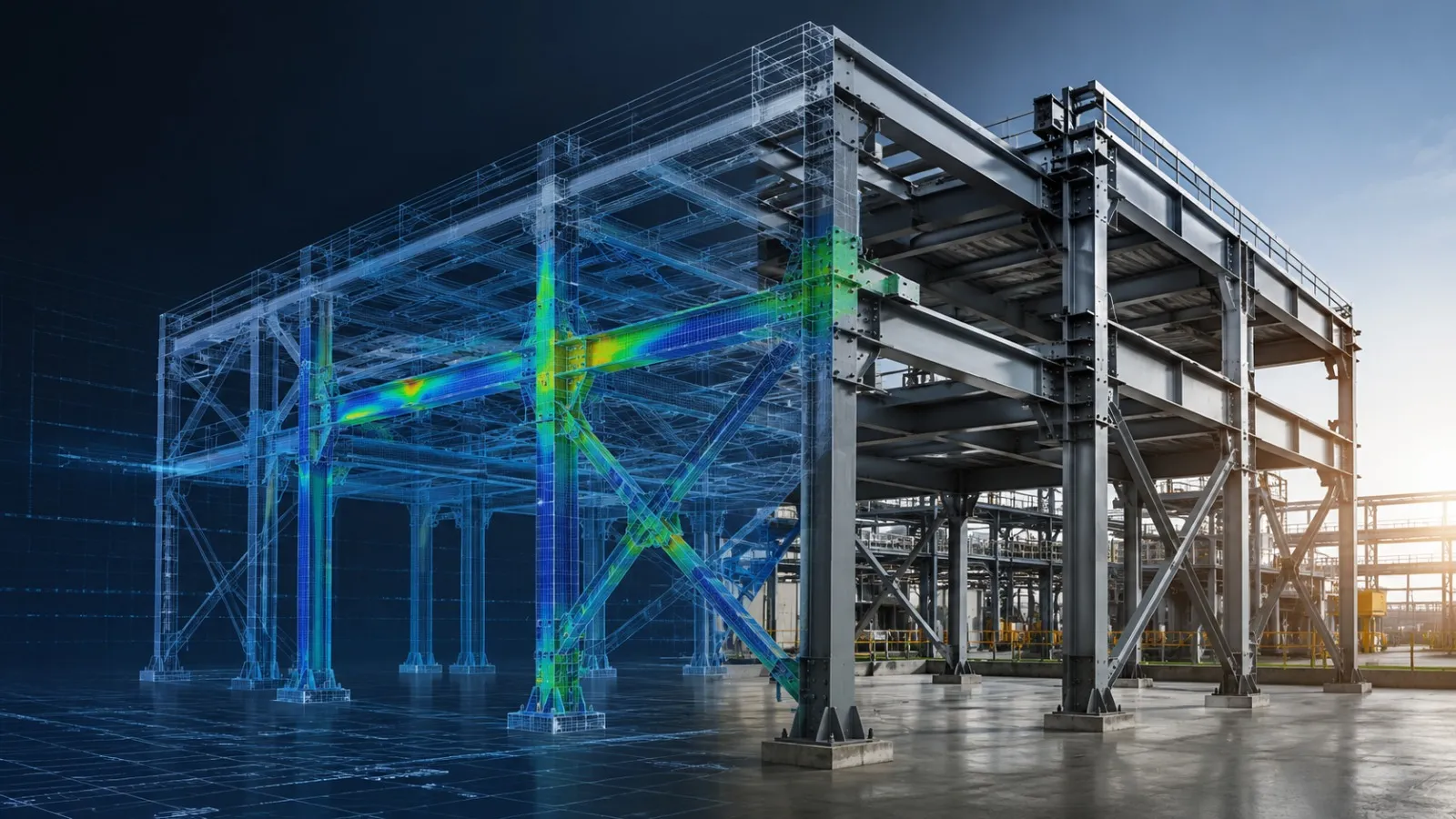
By evaluating connection forces, load paths, geometry, member behavior, and constructability before fabrication, engineers can identify potential problems while changes are still being made in the digital design environment.
A well-integrated workflow can therefore follow:
Structural Analysis → Connection Design → 3D Detailing → Fabrication Drawings → Manufacturing
This approach helps reduce design-related rework, improve fabrication coordination, and create more reliable fabrication-ready structural steel designs.
What Is Structural Connection Design?
Structural connection design is the engineering process of designing the interfaces that transfer forces between structural members.
Depending on the structure and its intended behavior, connections may include:
- Beam-to-column connections
- Beam-to-beam connections
- Column splices
- Base plate and anchor rod connections
- Bracing connections
- Gusset plate connections
- Moment connections
- Shear connections
- Bolted connections
- Welded connections
- Equipment support connections
- Structural frame connections
A connection is not simply a collection of bolts, welds, and plates.
It is part of the structural load path.
For example:
Equipment Load → Beam → Connection → Column → Base Plate → Foundation
Every interface in this load path must transfer the required forces appropriately.
Structural analysis provides the forces and reactions that become critical inputs for connection design.
Why Connection Design Matters Before Fabrication
A structural connection can satisfy the overall design intent while still creating practical fabrication problems.
For example, a connection detail may require:
- Excessively thick plates
- Difficult weld access
- Closely spaced bolts
- Insufficient edge distance
- Conflicting stiffeners
- Difficult assembly access
- Unnecessary fabrication operations
- Unclear shop drawing information
This is also why structural analysis before steel fabrication is important for identifying design-related issues while changes can still be made digitally.
The AISC Specification addresses fabrication and erection documentation and requires shop drawings to provide the information necessary to fabricate component parts, including the location, type, and size of welds and bolts.
This demonstrates an important principle:
Connection design should be developed with fabrication and erection in mind, not treated as an isolated calculation exercise.
How Structural Analysis Supports Connection Design
Structural analysis provides the engineering information required to understand what a connection needs to transfer.
Depending on the structural system, analysis can provide:
- Axial forces
- Shear forces
- Bending moments
- Torsional forces
- Support reactions
- Combined loading
- Load combinations
- Member utilization
- Structural deflection
- Stability behavior
These results can then be used to develop appropriate connection details.
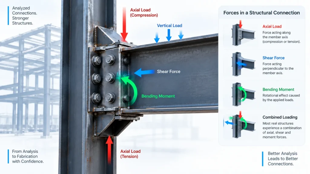
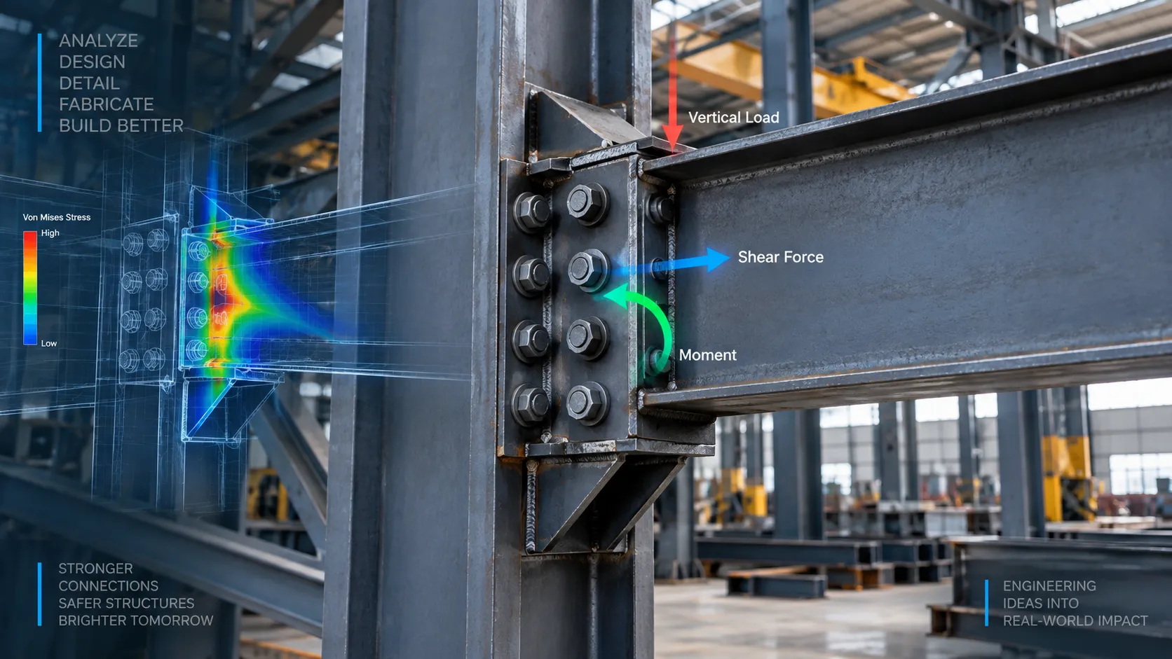
For example, a beam-to-column connection may experience a combination of shear and moment. The connection design must account for the resulting force transfer rather than simply selecting a standard detail based on the beam size.
This creates a direct relationship:
Analysis Results → Connection Forces → Connection Design → Fabrication Detail
When these stages are disconnected, design inconsistencies can occur.
1. Analysis Helps Identify Critical Connection Forces
One of the first benefits of structural analysis is identifying where significant forces occur.
Not every connection in a structure experiences the same loading.
A steel frame may contain:
- Lightly loaded secondary connections
- High-shear beam connections
- Moment-resisting connections
- Highly loaded brace connections
- Column splices
- Heavy equipment support connections
Structural analysis helps identify the critical locations that require detailed engineering review.
For example, a brace connection may experience high axial force even though the brace itself appears relatively small.
Without analyzing the actual structural load path, the connection could be designed using an inappropriate assumption.
Analysis therefore helps answer:
Where are the highest connection demands in the structure?
2. Analysis Validates the Load Path
A connection should not be designed independently from the structure around it.
Consider an industrial equipment platform.
The equipment load transfers through:
Equipment → Support Beam → Beam Connection → Column → Base Plate → Foundation
If the connection between the beam and column is inadequate, the load path is interrupted.
Structural analysis helps engineers evaluate how loads travel through the overall structure and how forces are distributed between members.
This is especially important for:
- Equipment support structures
- Industrial platforms
- Pipe racks
- Steel frames
- Skid structures
- Access platforms
- Heavy machinery supports
- Structural towers
A connection design should reflect the actual structural behavior rather than only the geometry of the members being joined.
3. Connection Design Can Be Validated Before Detailing
A common workflow problem occurs when detailed 3D modeling begins before connection requirements have been fully established.
The model may look complete, but later connection calculations can require:
- Larger plates
- Additional stiffeners
- Different bolt patterns
- Modified member geometry
- Additional bracing
- Increased weld sizes
- Revised connection orientation
These changes can then propagate through the entire fabrication model.
A better approach is to validate major connection requirements before final detailing.
The workflow can be:
Preliminary Model
↓
Structural Analysis
↓
Critical Connection Identification
↓
Connection Design
↓
Detailed Structural Model
↓
Fabrication Drawings
This reduces the likelihood of major changes occurring after detailing.
4. Analysis Helps Prevent Undersized Connection Components
A connection may fail even when the connected structural members are adequately sized.
Connection components can include:
- Connection plates
- Gusset plates
- End plates
- Base plates
- Stiffeners
- Angles
- Cleats
- Bolts
- Welds
- Anchor rods
Each component must be appropriate for the forces being transferred.
For example, a heavily loaded beam may require a connection plate capable of transferring significant shear and moment.
If the plate is too thin, local deformation or other connection-specific limit states may become important.
Similarly, a gusset plate supporting a brace must be evaluated for the forces transferred through the brace and surrounding structural members.
Early connection design allows these components to be optimized before fabrication drawings are released.
5. Analysis Helps Improve Bolted Connection Design
Bolted connections are widely used because they can simplify assembly and field erection.
However, their design involves more than selecting a bolt diameter.
Engineers may need to consider:
- Number of bolts
- Bolt diameter
- Bolt grade
- Bolt spacing
- Edge distance
- Hole configuration
- Plate thickness
- Shear
- Tension
- Bearing
- Slip requirements where applicable
- Connection geometry
- Installation access
The RCSC Specification provides requirements for the design of bolted structural joints and installation and inspection of high-strength fastener assemblies.
AISC connection guidance also addresses different hole configurations, including standard, oversized, short-slotted, and long-slotted holes.
From a fabrication perspective, the bolt pattern must also be practical.
A theoretically adequate connection can still create problems if:
- Bolts are too close to adjacent plates
- Tools cannot access the bolts
- Hole locations conflict with stiffeners
- Edge distances are inadequate
- Multiple members compete for the same space
Therefore, bolt design should be reviewed from both structural and fabrication perspectives.
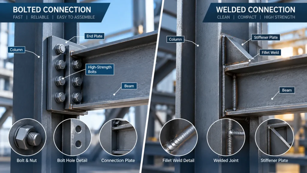
6. Analysis Helps Improve Welded Connection Design
Welded connections are another major area where structural requirements and fabrication requirements must be coordinated.
Depending on the application, engineers may need to evaluate:
- Weld type
- Weld size
- Weld length
- Load direction
- Combined loading
- Plate thickness
- Access for welding
- Weld sequence
- Connection geometry
A connection may require a particular weld arrangement based on the forces predicted by the structural analysis.
However, the detail should also allow the fabricator to execute the weld correctly.
This is why fabrication-ready connection design considers more than calculated capacity.
The question is not only:
“Can the weld transfer the required load?”
It is also:
“Can this weld be practically fabricated, inspected, and assembled?”
7. Analysis Helps Identify Base Plate and Anchor Rod Problems
Column base connections are particularly important because they transfer structural forces into the foundation.
Depending on the structural system, a base connection may transfer:
- Compression
- Tension
- Shear
- Moment
- Combined forces
The analysis results determine the forces that need to be considered in the base connection.
Connection design may then involve:
- Base plate dimensions
- Plate thickness
- Anchor rod arrangement
- Stiffeners
- Welds
- Shear transfer
- Foundation interface
If these requirements are discovered after fabrication, changing the base plate or anchor rod configuration can become disruptive.
Early analysis and connection design allow these interfaces to be coordinated with the foundation and surrounding structure before production.
8. Analysis Helps Detect Geometry Problems Before Steel Is Cut
Not all connection problems are strength problems.
Geometry can be equally important.
A connection detail should be reviewed for:
- Member alignment
- Plate clearances
- Bolt access
- Welding access
- Stiffener interference
- Adjacent member conflicts
- Equipment clearances
- Erection access
- Assembly sequence
AISC guidance on fabrication and erection tolerances recognizes that dimensional deviations and tolerance accumulation can affect connection fit-up and erection.
This is particularly relevant in complex industrial structures where several members meet in a relatively small region.
A connection may work mathematically but become difficult to fabricate or erect because multiple components occupy the same space.
3D structural detailing can help identify these conflicts before fabrication.
9. Connection Design Should Consider Fabrication Tolerances
Fabricated steel components are not produced with infinitely precise dimensions.
Fabrication and erection standards establish permissible tolerances, and project-specific requirements may impose additional criteria.
Connection design therefore needs to accommodate realistic fabrication and erection conditions.
This can include consideration of:
- Hole tolerances
- Member dimensional tolerances
- Plate alignment
- Member straightness
- Erection clearances
- Connection fit-up
- Accumulated tolerances
For example, a connection with extremely tight geometric requirements may be difficult to erect even when every individual component has been fabricated within its permitted tolerance.
Good connection detailing anticipates these conditions.
Common Fabrication Problems Related to Connection Design
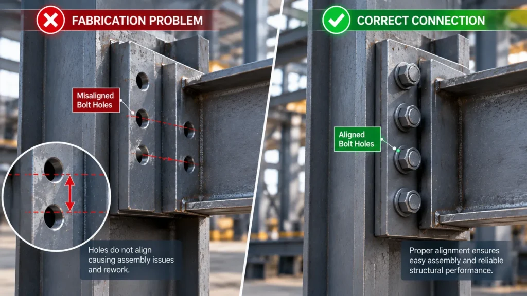
Several fabrication problems can originate from inadequate or incomplete connection design.
- Misaligned Bolt Holes: Incorrect hole locations can prevent members from being assembled properly.
- Insufficient Edge Distance: Bolt holes positioned too close to plate edges can create structural and fabrication concerns.
- Weld Access Problems: A connection may require welding in a location that is difficult or impractical to access.
- Plate Interference: Connection plates or stiffeners may interfere with adjacent members.
- Incorrect Connection Orientation: A connection may be detailed differently from the orientation assumed during design.
- Excessive Connection Complexity: An unnecessarily complicated connection can increase fabrication time and introduce more opportunities for errors.
- Assembly Problems: Components may be individually correct but difficult to assemble because the connection sequence was not considered.
- Last-Minute Design Changes: Connection changes made after fabrication drawings are released can create revision and rework cycles.
The AISC Solutions Center specifically identifies fabrication deviations such as incorrect member lengths, misplaced holes, and incorrectly located parts as issues that may require engineering evaluation.
The objective of connection-focused engineering is to reduce the likelihood that design problems reach this stage.
Structural Analysis vs. Connection Detailing
Structural analysis and structural detailing serve different purposes, but they need to remain coordinated.
| Structural Analysis | Connection Detailing |
|---|---|
| Determines member forces | Converts design requirements into physical details |
| Evaluates structural behavior | Defines plates, bolts and welds |
| Calculates reactions | Defines connection geometry |
| Checks deflection | Provides fabrication dimensions |
| Evaluates stability | Coordinates assembly interfaces |
| Identifies critical locations | Produces fabrication-ready documentation |
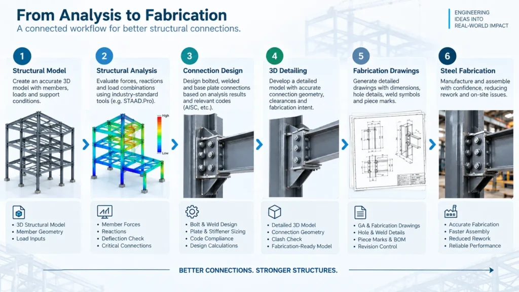
The complete engineering workflow should connect both activities.
Structural Analysis
↓
Connection Forces
↓
Connection Design
↓
3D Structural Detailing
↓
Shop Drawings
↓
Fabrication
This connection between engineering and detailing is essential for fabrication-oriented structural projects.
A Practical Workflow for Structural Connection Design
A structured workflow can help reduce connection-related fabrication problems.
Step 1: Understand the Structural Requirements
Review:
- Structural geometry
- Member sizes
- Material grades
- Design loads
- Load combinations
- Support conditions
- Applicable design standards
- Fabrication requirements
- Erection requirements
Step 2: Perform Structural Analysis
Evaluate the structural system under the applicable load cases.
Review:
- Member forces
- Reactions
- Deflections
- Stability
- Critical load combinations
Step 3: Identify Critical Connections
Determine which connections experience significant:
- Shear
- Axial force
- Moment
- Torsion
- Combined loading
Step 4: Design the Connections
Develop appropriate:
- Bolt arrangements
- Weld details
- Plates
- Gussets
- Stiffeners
- Base plates
- Anchor rod configurations
Step 5: Review Constructability
Check:
- Bolt access
- Weld access
- Member clearance
- Plate interference
- Erection sequence
- Fabrication practicality
Step 6: Develop the Detailed 3D Model
Create a coordinated structural model containing the validated connection geometry.
Step 7: Prepare Fabrication Drawings
Fabrication documentation should clearly communicate:
- Dimensions
- Material
- Weld information
- Bolt information
- Hole locations
- Piece marks
- Assembly requirements
- Revision information
AISC guidance emphasizes that shop drawings need to provide the information necessary for fabrication and erection.
Step 8: Final Pre-Fabrication Review
Before releasing the project for production, review the complete connection and fabrication package.
The objective is to make sure that:
What was analyzed is what was detailed, and what was detailed is what will be fabricated.
Where FEA Fits Into Connection Design
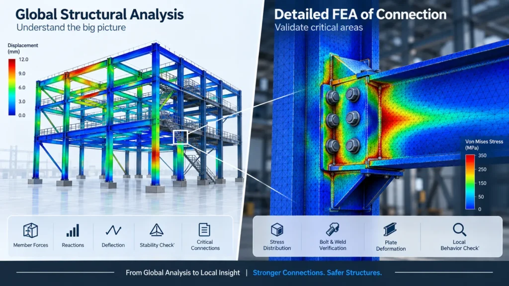
For many structural systems, global structural analysis is sufficient to establish member forces and connection demands.
However, some connection regions may require more detailed investigation.
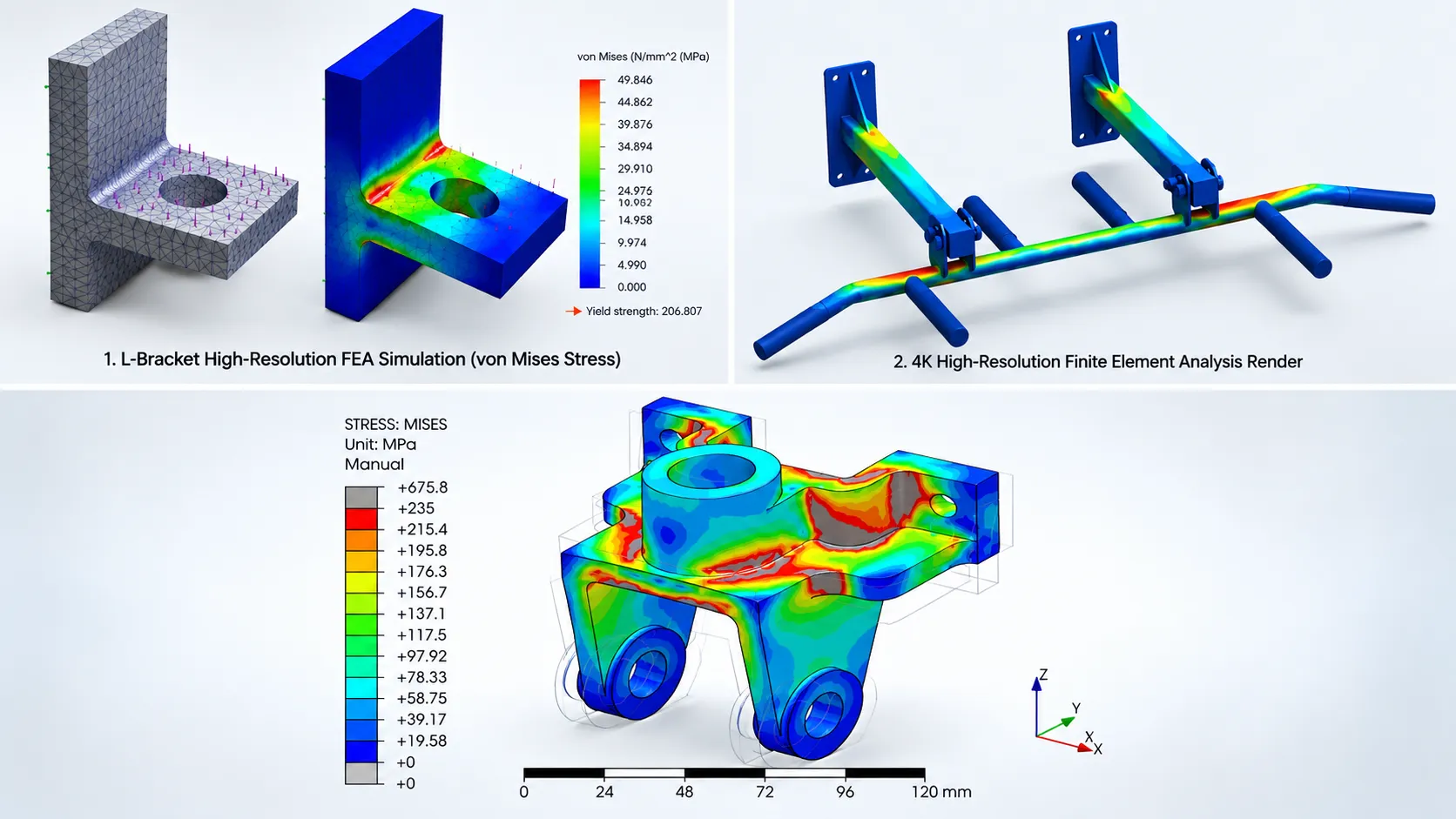
FEA can be useful for localized structural behavior such as:
- Base plates
- Gusset plates
- Brackets
- Equipment supports
- Complex welded joints
- Local stress concentrations
- Irregular connection geometries
- Local plate deformation
For example, a global structural model may identify a high reaction at an equipment support.
FEA simulation can be useful when localized behavior needs more detailed investigation, such as stress concentrations around connection plates, brackets, base plates, gusset plates, welded regions, or complex equipment supports.
This creates a two-level analysis approach:
Global Structural Analysis
→ Overall structural behavior and connection forces
Detailed FEA
→ Local behavior of critical connection regions
Using the appropriate analysis method at each stage can provide better engineering insight without unnecessarily increasing model complexity.
How 3D Detailing Helps Connect Analysis With Fabrication
Once the structural and connection design has been validated, 3D detailing becomes an important bridge between engineering and manufacturing.
A detailed model can help coordinate:
- Beam-to-column connections
- Bracing
- Gusset plates
- Stiffeners
- Base plates
- Bolt patterns
- Weld locations
- Member intersections
- Equipment interfaces
The model can then support fabrication drawings and other manufacturing documentation.
This digital connection between analysis and detailing helps reduce the possibility of information being lost during the transition from engineering calculations to fabrication.
What Should Be Checked Before Releasing Structural Connections for Fabrication?
A practical pre-fabrication connection review should include:
Structural Checks
- Connection forces
- Load combinations
- Member capacity
- Connection capacity
- Stability
- Deflection
- Load path
Bolt Checks
- Bolt size
- Bolt grade
- Quantity
- Spacing
- Edge distance
- Hole type
- Installation access
Weld Checks
- Weld type
- Weld size
- Weld length
- Weld accessibility
- Connection geometry
Geometry Checks
- Member alignment
- Plate clearances
- Stiffener interference
- Equipment clearance
- Assembly access
- Erection requirements
Fabrication Checks
- Plate thickness
- Material specification
- Hole locations
- Cutting requirements
- Weld symbols
- Piece marks
- Assembly information
Documentation Checks
- Design calculations
- Analysis results
- Connection details
- Shop drawings
- BOM
- Revision control
This review creates a final quality gate before the design moves into fabrication.
Benefits of Analysis-Driven Connection Design
Integrating structural analysis with connection design can provide several practical benefits.
- Reduced Fabrication Rework: Design issues can be identified before components are manufactured.
- Better Connection Reliability: Connection geometry is based on actual structural demands rather than assumptions alone.
- Improved Fabrication Coordination: Designers and fabricators receive clearer and more complete connection information.
- Reduced Design Changes: Early validation reduces the need for late-stage connection revisions.
- Better Material Utilization: Connection components can be sized according to actual engineering requirements.
- Improved Erection Planning: Connections can be reviewed for access, fit-up, and assembly requirements before reaching the site.
- Faster Engineering-to-Fabrication Transition: A validated connection model can move more efficiently into detailed drawings and production documentation.
How Immersiv Techsphere Supports Structural Engineering Workflows
Immersiv Techsphere supports engineering workflows that connect structural analysis, 3D modeling, detailing, and fabrication documentation.
The company’s engineering capabilities include structural analysis using tools such as STAAD Pro, 3D engineering design, fabrication drawings, and simulation support.
For projects involving fabricated steel structures and industrial equipment supports, an integrated workflow can include:
Structural Modeling → Analysis → Connection Design → 3D Detailing → Fabrication Drawings
This approach can support applications such as:
- Industrial steel structures
- Equipment support structures
- Platforms
- Structural frames
- Fabricated assemblies
- Machinery support structures
- Industrial access structures
- Steel detailing and fabrication documentation
Immersiv Techsphere also provides FEA-based engineering validation for fabricated structures and industrial equipment, including stress, deformation, and structural performance assessment.
The objective is to connect engineering analysis with practical manufacturing requirements so that the final design is not only structurally validated but also prepared for the next stage of production.
Frequently Asked Questions
Structural connection design is the engineering process of designing the interfaces between structural members so that forces can be safely and appropriately transferred through the structure.
Structural analysis provides forces and reactions such as shear, axial force, moment, and torsion. These results are used as inputs for designing appropriate structural connections.
Structural analysis can help prevent design-related fabrication problems by identifying inadequate member sizes, excessive deflection, unexpected reactions, critical connection forces, and other issues before fabrication begins.
Common structural steel connections include bolted connections, welded connections, shear connections, moment connections, bracing connections, beam-to-column connections, column splices, and base plate connections.
3D review helps identify spatial conflicts, plate interference, bolt access problems, welding access issues, member alignment problems, and coordination issues that may not be obvious in isolated 2D connection details.
FEA can be useful when localized behavior needs more detailed investigation, such as stress concentrations around connection plates, brackets, base plates, gusset plates, welded regions, or complex equipment supports.
Structural analysis evaluates how the structure behaves under defined loads. Structural detailing converts the approved structural design into detailed geometry and fabrication information such as plates, bolts, welds, dimensions, and piece marks.
The review should consider structural capacity, connection forces, bolt and weld requirements, geometry, fabrication access, erection requirements, tolerances, material specifications, and fabrication documentation.
Conclusion
Structural connection design sits at the intersection of structural engineering and fabrication.
A connection is not successful simply because it satisfies a calculation. It also needs to work within the geometry of the structure, fabrication processes, assembly requirements, erection tolerances, and available access.
Structural analysis provides the foundation by identifying the forces and behavior that connections must accommodate.
Connection design converts those requirements into practical structural details.
3D detailing then translates those details into fabrication-ready information.
The complete workflow can be summarized as:
Analyze → Design Connections → Validate → Detail → Document → Fabricate
By identifying connection and structural issues before steel reaches the fabrication shop, engineering teams can reduce rework, improve coordination, and create a more predictable transition from structural design to manufacturing.
For fabrication-focused steel projects, the objective is not simply to design a connection that works mathematically.
The objective is to design a connection that works structurally, geometrically, and practically in fabrication and erection.
Have a Project in Mind?
Need help with 3D animation, industrial visualization, HSE training animation, or product visualization? Tell us about your project and our team will get back to you.