

Table of Contents
Introduction
Welded structures are widely used in industrial equipment, machine frames, material handling systems, platforms, support structures and manufacturing assemblies. From a mechanical design engineer’s perspective, designing a weldment is not simply about connecting a few steel members. It involves selecting suitable profiles, defining accurate member lengths, planning joints, considering fabrication constraints and preparing drawings that a manufacturing team can follow without confusion.
A 3D model may look correct on the screen, but that does not necessarily mean it is ready for fabrication.
A successful Weldment Design for Manufacturing workflow considers how individual members will be cut, positioned, welded, inspected and assembled. It also ensures that the required information is communicated through engineering drawings, cut lists and material specifications.
Let’s understand the important considerations involved in developing manufacturing-ready weldment designs.
Start with Structural Requirements Before Selecting Profiles
The first step in weldment design is understanding the purpose of the structure.
Before selecting square tubes, rectangular hollow sections (RHS), channels, angles or I-beams, a mechanical design engineer needs to understand the loads, support conditions, operating environment and functional requirements.
For example, a machine frame may need to support:
- The weight of equipment and mounted components.
- Static and dynamic operating loads.
- Vibrations generated by rotating machinery.
- Forces transferred through mounting points.
- Transportation and handling loads.
These requirements influence the selection of structural members, material grades, wall thicknesses and connection arrangements.
For applications involving significant structural loads, the design should also be checked using appropriate engineering calculations or structural analysis. The member selection should not be based only on visual appearance or available stock sizes.
Another important consideration is manufacturing availability. Selecting a standard profile that is readily available from local suppliers can simplify procurement and reduce material wastage.
Selecting the Right Structural Profiles
Structural profiles form the foundation of most weldment designs. Their selection directly affects structural performance, fabrication effort, material consumption and overall cost.
Common profiles used in welded structures include:
- Square Hollow Sections (SHS): Used in machine frames, equipment stands and support structures.
- Rectangular Hollow Sections (RHS): Suitable for frames requiring different stiffness characteristics along two directions.
- Circular Hollow Sections (CHS): Used in tubular frames, supports and structures where round sections are required.
- Equal and Unequal Angles: Commonly used for brackets, supports and secondary structural members.
- C-Channels and U-Channels: Used in equipment frames, mounting structures and support arrangements.
- I-Beams and H-Beams: Used in applications requiring higher bending resistance.
Profile selection should consider more than cross-sectional dimensions.
A mechanical design engineer should evaluate:
- Material grade: Confirm that the selected material meets the required strength, weldability and environmental requirements.
- Wall thickness: Check whether the thickness is suitable for the expected loads, welding process and connection details.
- Profile availability: Prefer standard, commercially available sections wherever practical.
- Welding accessibility: Ensure that the selected profile allows sufficient access for the required welding operations.
- Corrosion protection: Consider whether the structure will require painting, galvanizing or another protective coating.
For example, a machine frame designed using a 50 × 50 × 3 mm square tube should not be considered finalized simply because the dimensions fit the available space. Its suitability must also be evaluated against loading, deflection, connection details and manufacturing requirements.
Managing Weldment Profiles in SolidWorks
When working with structural frames, CAD software helps engineers develop consistent models using predefined structural profiles.
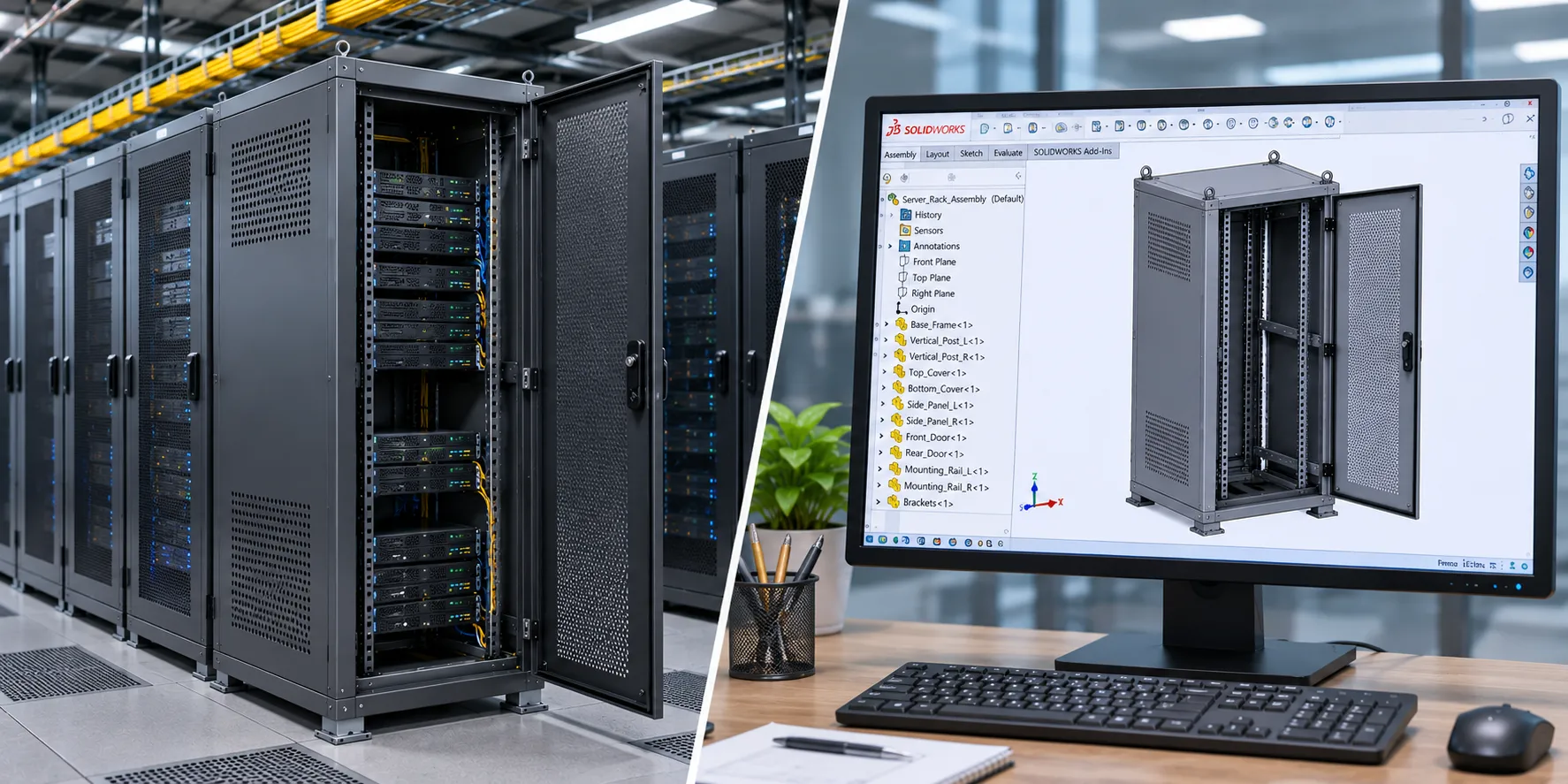
SolidWorks Weldments is particularly useful for creating multibody structural designs. Engineers can use sketch lines as reference paths and apply standard or custom structural profiles to generate individual members.
A typical SolidWorks weldment workflow includes:
- Create a 2D or 3D sketch representing the structural framework.
- Select the required sketch segments.
- Apply structural members using the appropriate profile library.
- Define member groups and profile orientation.
- Adjust profile positioning using alignment and pierce-point settings.
- Apply Trim/Extend operations to manage member intersections.
- Add plates, gussets, end caps and other required components.
- Update and review the weldment cut list.
One important aspect is maintaining a standardized weldment profile library.
Engineers should organize profiles according to standards, material types and dimensions. Custom profiles may also be required when a company uses special sections that are not available in the default library.
Incorrect profile definitions or inconsistent library naming can create problems when multiple engineers work on the same design.
It is also important to verify the profile orientation and insertion point. A profile applied to the correct sketch line can still be positioned incorrectly if its alignment or pierce point is not properly defined.
Trim and Extend: Making Structural Members Fabrication-Ready
One of the most important stages of weldment modelling is managing member intersections.
In an actual fabrication workshop, structural members cannot simply overlap wherever two profiles meet. Their ends must be prepared to create the intended joint configuration.
Common member connection arrangements include:
- Butt joints.
- T-joints.
- Corner joints.
- Miter joints.
- Lap joints.
The appropriate arrangement depends on the structural requirements, welding process and fabrication sequence.
In SolidWorks, the Trim/Extend feature helps engineers manage these intersections by trimming or extending structural members relative to other bodies or selected faces and planes.
However, the objective is not just to remove overlapping geometry.
The engineer must consider:
- Which member should remain continuous?
- Which member should be cut to fit against the other?
- Is the required weld accessible?
- Is there sufficient clearance for welding equipment?
- Will the joint be practical to fabricate and inspect?
For example, in a rectangular machine frame, the corner connection may use a mitered joint or a butt arrangement depending on the fabrication approach.
Both can produce valid CAD geometry, but the preferred arrangement should be decided based on structural requirements, welding access and workshop practices.
The final model should represent the intended fabrication arrangement rather than an arbitrary geometric intersection.
Cut List Management: Connecting CAD Models with Manufacturing
A weldment model becomes significantly more useful when its manufacturing information is properly organized.
This is where the Weldment Cut List plays an important role.
A cut list identifies the individual structural members required to manufacture the assembly. It can group equivalent bodies and provide information such as profile description, material, length, quantity and cutting details.
For example, consider a machine frame containing:
| Structural member | Profile | Quantity |
|---|---|---|
| Main longitudinal members | SHS 50 × 50 × 3 mm | 2 |
| Cross members | SHS 40 × 40 × 3 mm | 4 |
| Vertical supports | SHS 50 × 50 × 3 mm | 4 |
| Diagonal supports | RHS 40 × 20 × 3 mm | 2 |
This information gives the fabrication team a starting point for material planning and cutting operations.
In SolidWorks, the cut list is generated from the individual bodies in the weldment part. Similar bodies can be grouped into cut-list items, depending on their geometry and properties.
However, engineers should not assume that the automatically generated cut list is always ready for production.
It needs to be reviewed after design changes, particularly when members are modified, replaced or repositioned.
Important cut list properties
A useful weldment cut list should include:
- Item number: Unique identification for each cut-list entry.
- Profile description: Section type and dimensions.
- Material: Required material grade or specification.
- Cut length: Required member length based on the defined modelling and cutting convention.
- Quantity: Number of identical members.
- Cut angle: Relevant end-cut information where required.
- Part or member identification: A reference that connects the cut list to the drawing.
Additional properties such as surface finish, coating requirements and stock identification can also be included.
A key engineering consideration is the distinction between member length and raw material procurement length.
For example, a member with a finished cut length of 1,250 mm does not automatically mean that the supplier should provide a 1,250 mm raw stock piece. Procurement also depends on stock availability, cutting allowance, saw kerf, nesting arrangements and material optimization.
These requirements should be clearly managed during production planning.
Designing Weldment Joints, Gussets and Reinforcement Plates
Structural members often require additional plates and reinforcements to complete the design.
Gussets, mounting plates, stiffeners, end caps and connection plates are commonly used in welded structures.
However, their placement should be based on engineering requirements rather than simply adding material to make a structure appear stronger.
Consider the following design aspects:
- Gusset placement: Gussets can reinforce connections between intersecting members. Their size, thickness and location should be evaluated against the applied loads and connection design.
- Mounting plates: These provide interfaces for mounting motors, gearboxes, equipment and other assemblies. Their thickness, hole positions and flatness requirements need to be considered.
- End caps: These close open tube sections where required. Their design should also account for drainage, venting or sealing requirements depending on the application and coating process.
- Stiffener plates: These may be necessary to improve local stiffness or support concentrated loads.
Another important consideration is weld accessibility. A joint that is difficult to reach may increase fabrication time and create inspection challenges.
The designer should coordinate the connection details with the fabrication team, especially for complex or heavily loaded structures.
Assembly Requirements and Fabrication Sequence
A weldment may contain correctly selected profiles and accurate cut lengths but still create assembly problems during fabrication.
This usually happens when the design does not consider the actual manufacturing sequence.
For example, a frame with several cross members, mounting plates and gussets may require a defined assembly arrangement to maintain alignment and dimensional accuracy.
Before releasing the design, engineers should consider:
- Assembly sequence: Determine which members need to be positioned and joined first, and which components should be installed later.
- Welding access: Ensure that weld locations are accessible without interference from neighbouring members.
- Fixture requirements: Identify whether jigs, clamps or locating fixtures will be needed to maintain the required geometry.
- Dimensional control: Identify critical dimensions such as mounting-hole locations, frame diagonals, parallelism and overall flatness.
- Welding distortion: Consider the effects of heat input and welding sequence on the final geometry.
Welding can introduce residual stresses and dimensional distortion. For larger frames, an appropriate welding sequence and balanced welding approach may be necessary to control deformation.
The final assembly should also allow sufficient space for installation of fasteners, tools, cables, pipes and other connected components.
These considerations are particularly important for machine frames, industrial equipment structures and skid-mounted assemblies.
Manufacturing Drawings: Communicating Design Intent Clearly
A 3D model communicates the overall geometry, but fabrication teams generally need detailed manufacturing drawings to complete the work.
A good weldment drawing should clearly communicate what needs to be cut, positioned, welded and inspected.
Depending on the project, the drawing package may include:
- General arrangement drawing.
- Individual member and plate details.
- Weldment assembly drawing.
- Structural member cut list.
- Welding symbols and joint details.
- Material specifications.
- Dimensional and geometric tolerances.
- Surface finish and coating requirements.
Welding symbols should follow the applicable drawing standard, such as ISO 2553 or AWS A2.4, depending on the project requirements.
Similarly, general tolerances for welded constructions may be specified using ISO 13920:2023 where applicable. The selected tolerance class should reflect the functional requirements and expected fabrication capability.
One common mistake is providing an overall frame dimension without identifying the critical dimensions needed to position individual members.
For example, if a machine frame requires four mounting holes to align with a motor base, the drawing should clearly communicate their locations and relevant tolerances.
The fabrication team should not have to estimate these dimensions from a 3D model.
The objective is to reduce interpretation, avoid unnecessary clarification and provide a reliable manufacturing reference.
Common Weldment Design Mistakes to Avoid
Even experienced design teams can encounter manufacturing problems when certain details are overlooked.
Here are some common issues to check before releasing a weldment design:
- Using non-standard profiles unnecessarily: Custom profiles can increase procurement and manufacturing complexity. Standard sections should be considered wherever they satisfy the engineering requirements.
- Incorrect member positioning: Incorrect profile orientation or insertion points can affect dimensions, clearances and joint geometry.
- Overlapping structural members: Untrimmed or incorrectly trimmed members can create confusion during fabrication and result in incorrect cut lengths.
- Incomplete cut list information: Missing material specifications, descriptions or member lengths can lead to procurement and cutting errors.
- Ignoring welding distortion: Long welded structures may experience dimensional changes due to heat input. Welding sequence and fabrication methods should be considered during design.
- Missing assembly clearances: Insufficient space for tools, fasteners and welding operations can make an otherwise correct design difficult to manufacture.
- Inadequate manufacturing drawings: A detailed 3D model cannot replace clearly defined fabrication drawings, welding requirements and dimensional controls.
Addressing these issues during the design stage is generally easier than correcting them after fabrication has started.
How CAD Automation Improves Weldment Design Workflows
When engineering teams regularly work on similar structural frames, manual modelling and drawing preparation can consume considerable time.
CAD automation can help standardize repetitive engineering activities and improve consistency across projects.
For SolidWorks-based weldment workflows, automation using the SolidWorks API, VBA macros and .NET can support activities such as:
- Extracting structural member properties from weldment models.
- Exporting cut list information into Excel.
- Generating standardized member identification numbers.
- Preparing material and quantity reports.
- Automating drawing and PDF exports.
- Creating structured manufacturing documentation.
- Checking selected custom properties for missing information.
For example, a company manufacturing multiple machine frames may follow a common cut list format for every project.
Instead of manually collecting member information and preparing separate Excel reports, a customized automation tool can extract the relevant properties and organize them into a predefined format.
However, automation should not replace engineering verification. The accuracy of the output still depends on correctly modelled geometry, updated cut lists, consistent properties and appropriate validation rules.
For companies handling repetitive weldment designs, combining SolidWorks modelling with CAD automation can make the design-to-manufacturing workflow more consistent and manageable.
Conclusion
Weldment design for manufacturing requires more than creating a structural frame in CAD. It involves making the right decisions about profile selection, member positioning, joint arrangements, cut list properties, assembly sequence and fabrication documentation.
A manufacturing-ready weldment model should clearly communicate what needs to be manufactured, how individual members fit together and what information the fabrication team needs to complete the structure.
By following a structured approach to SolidWorks Weldment Design, Cut List Management and Manufacturing Drawing Preparation, mechanical design engineers can reduce avoidable fabrication issues and create more reliable engineering deliverables.
At Immersiv Techsphere, we work on mechanical design, structural modelling, fabrication drawings and CAD automation to help engineering teams develop practical, manufacturing-oriented design workflows.
The objective is not just to create a model that looks right, but to develop a design that can be manufactured, assembled and used as intended.
Have a Project in Mind?
Need help with 3D animation, industrial visualization, HSE training animation, or product visualization? Tell us about your project and our team will get back to you.