

Table of Contents
Introduction
A steel structure can be structurally sound on paper but still create problems during fabrication if design assumptions, member sizes, connections, dimensions, or load paths are not properly validated before production.
Once steel reaches the fabrication shop, correcting a design-related issue can become expensive. A member may already be cut, holes drilled, plates welded, or components assembled. Changing the design at this stage can lead to material waste, production delays, rework, and coordination problems.
This is where structural analysis becomes an important part of the engineering workflow.
By evaluating a steel structure before fabrication, engineers can identify overstressed members, excessive deflection, instability, inadequate connections, unrealistic load paths, and other design issues while changes are still relatively easy to make.
AISC guidance also emphasizes the importance of understanding load paths in structural analysis and connection design, while its fabrication guidance recognizes issues such as incorrect member lengths, misplaced holes, and incorrectly located parts as common fabrication deviations.
The objective is not simply to produce a stronger structure. It is to validate the design before manufacturing begins.
What Is Structural Analysis in Steel Structure Design?
Structural analysis is the engineering process used to determine how a structure responds to applied loads and whether its members and connections can safely carry those loads.
For a steel structure, analysis can evaluate:
- Dead loads
- Live loads
- Wind loads
- Seismic loads
- Equipment loads
- Impact or moving loads
- Temperature effects
- Operational loads
- Load combinations
- Member forces and reactions
- Deflection
- Stability and buckling
- Connection forces
- Overall structural behavior
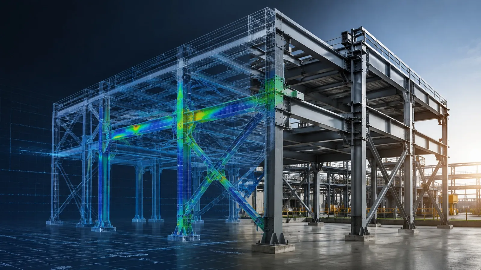
Depending on the project, engineers may use analytical methods ranging from conventional calculations to finite element analysis (FEA) and advanced numerical simulation.
The analysis model provides an opportunity to test the structural concept before material is purchased and fabrication starts.
This creates an important engineering principle: find design problems in the digital model before they become fabrication problems in the workshop.
Why Steel Fabrication Errors Often Begin Before Fabrication
Not every fabrication error originates in the fabrication shop.
Some problems are introduced earlier through:
- Incorrect design assumptions
- Incomplete load cases
- Incorrect member sizing
- Inadequate bracing
- Incorrect connection assumptions
- Missing load paths
- Dimensional inconsistencies
- Coordination issues between structural and equipment models
- Incorrect interpretation of design drawings
- Insufficient design verification
For example, if a beam has been designed without considering an actual equipment load, the fabrication drawing may accurately represent the design but still produce an inadequate structure.
Similarly, if a connection detail does not reflect the forces generated by the structural model, fabrication may proceed correctly according to the drawing while the underlying design remains problematic.
AISC’s steel design requirements state that member and connection design should be consistent with the intended behavior of the framing system and the assumptions used in structural analysis.
This demonstrates why structural analysis should not be treated as a separate activity performed after detailing. It should inform the design and fabrication workflow.
How Structural Analysis Helps Prevent Steel Fabrication Errors
1. Identifying Incorrect Member Sizes Before Cutting Steel
One of the most direct benefits of structural analysis is verifying whether beams, columns, braces, plates, and other structural members are appropriately sized.
Without analysis, member selection may rely heavily on preliminary calculations, previous projects, or engineering judgment.
Structural analysis provides quantitative information about:
- Axial forces
- Shear forces
- Bending moments
- Torsional effects
- Combined loading
- Stress utilization
- Deflection
- Stability
If a beam is undersized, the issue can be identified before the fabrication drawing is released.
Likewise, analysis can reveal when a member is unnecessarily oversized, creating opportunities to optimize material usage without compromising structural performance.
Example
Consider a steel platform supporting industrial equipment.
The initial design may specify a particular beam section based on estimated loads. After the equipment loads, support conditions, and load combinations are incorporated into the structural model, analysis may show excessive deflection.
The engineer can modify the beam size or structural arrangement before fabrication.
This is significantly easier than replacing a fabricated beam after production.
2. Checking Load Paths in a Steel Structure
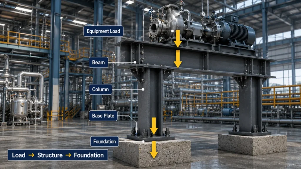
A steel structure must have a logical and continuous load path from the point where a load is applied to the supporting foundation.
For example:
Equipment → Supporting Beam → Column → Base Plate → Foundation
If one component in this path is incorrectly designed or insufficiently connected, the entire load-transfer mechanism can be affected.
Structural analysis helps engineers understand how forces move through the structure and identify unexpected force concentrations.
AISC specifically identifies load paths as a critical consideration in structural analysis and connection design.
Why this matters for fabrication
A problem in the load path can lead to:
- Incorrect connection plate thickness
- Insufficient stiffeners
- Incorrect beam selection
- Inadequate bracing
- Unexpected reactions
- Unanticipated connection forces
Finding these conditions during analysis gives the design team an opportunity to correct them before fabrication.
3. Detecting Excessive Deflection Before Production
A structure can satisfy strength requirements and still experience excessive deformation.
For steel structures supporting equipment, platforms, walkways, machinery, architectural components, or sensitive systems, excessive deflection may affect:
- Equipment alignment
- Door or panel operation
- Floor levels
- Connected piping
- Cladding
- Architectural finishes
- Serviceability
- User comfort
Structural analysis can calculate expected deformation under relevant load cases and combinations.
If the predicted displacement exceeds the project’s allowable criteria, engineers can modify the design before production.
Possible solutions may include:
- Increasing member stiffness
- Adding intermediate supports
- Adding bracing
- Changing member geometry
- Reducing unsupported spans
- Modifying the structural layout
This makes analysis a design optimization tool rather than simply a pass/fail calculation.
4. Finding Buckling and Stability Risks
Steel members subjected to compression can experience buckling even when their material strength appears adequate.
This is particularly important for:
- Columns
- Compression braces
- Long slender members
- Frames
- Towers
- Industrial structures
- Equipment support structures
Structural analysis can help identify stability-sensitive members and evaluate whether the structural system has adequate bracing.
AISC’s current technical discussions also emphasize that assumptions made during structural analysis must remain consistent with detailing, fabrication, and erection because seemingly minor decisions can affect overall structural stability.
Before fabrication, engineers can review:
- Effective lengths
- Bracing locations
- Member slenderness
- Buckling behavior
- Frame stability
- Connection assumptions
- Boundary conditions
This can prevent a fabrication package from being produced around an unstable or inadequately braced configuration.
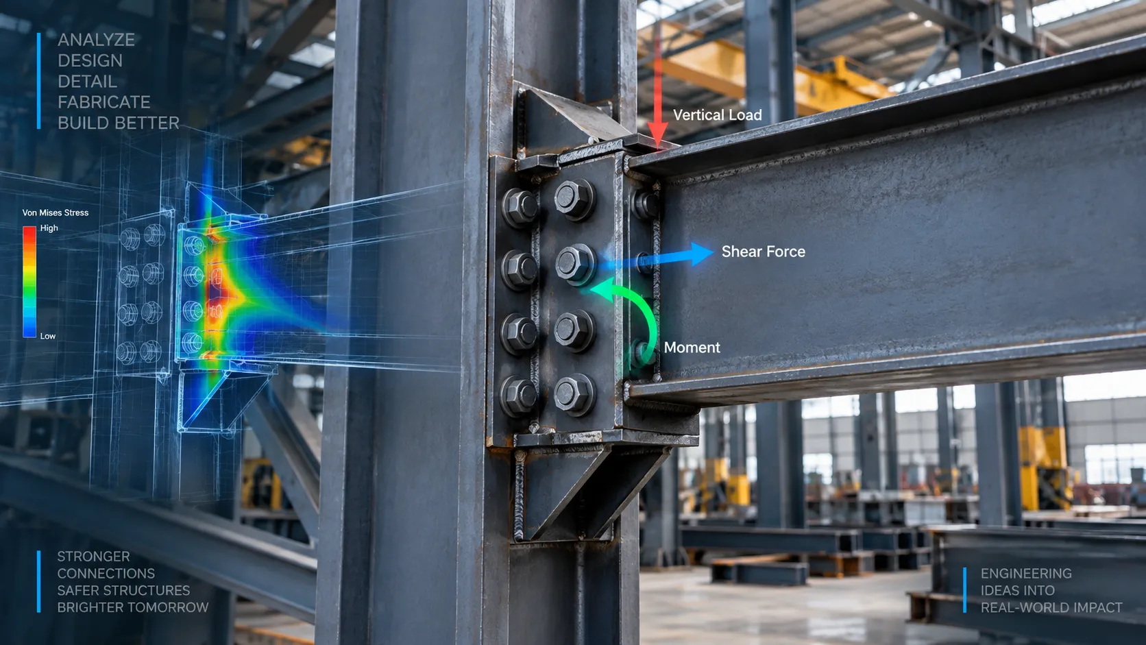
5. Validating Steel Connections Before Fabrication
Connections are among the most important interfaces between structural design and fabrication.
A connection must transfer the forces predicted by the structural analysis while remaining practical to manufacture and assemble.
Analysis can provide connection design inputs such as:
- Axial force
- Shear force
- Moment
- Reaction forces
- Combined loading
These forces can then inform the design of:
- Base plates
- Gusset plates
- End plates
- Cleat connections
- Bolted connections
- Welded connections
- Stiffeners
- Bracing connections
Incorrect connection assumptions can create significant problems later in the project.
For example, a connection may require a plate thickness or bolt arrangement different from the preliminary design. Discovering that difference after fabrication has started can require redesign and rework.
6. Checking Geometry Before Fabrication Drawings Are Released
Structural analysis is primarily concerned with structural behavior, but the analytical model also provides an opportunity to review the overall structural geometry.
Engineers can compare:
- Member locations
- Span dimensions
- Column positions
- Bracing arrangements
- Support locations
- Equipment interfaces
- Elevations
- Structural clearances
This is particularly valuable for complex industrial steel structures where structural members must coordinate with equipment, piping, platforms, access routes, or existing structures.
A structurally adequate design can still create fabrication or installation problems if the geometry is not coordinated.
Structural Analysis vs. Fabrication Drawings: Why Both Matter
Structural analysis and fabrication drawings serve different purposes.
| Structural Analysis | Fabrication Drawings |
|---|---|
| Validates structural behavior | Communicate manufacturing requirements |
| Calculates member forces | Defines member dimensions |
| Evaluates stress and utilization | Shows plates, holes, cuts and welds |
| Checks deflection | Provides fabrication dimensions |
| Evaluates stability | Defines connection geometry |
| Provides connection forces | Supports shop-floor production |
| Validates load paths | Communicates assembly requirements |
The strongest workflow connects these two stages. For projects that require both structural validation and fabrication-ready documentation, steel structure analysis and detailing services can help connect structural engineering decisions with detailed steel fabrication requirements.
Design → Structural Analysis → Design Verification → Detailing → Fabrication Drawings → Production
AISC fabrication guidance recognizes the importance of checking geometry, connections, holes, fasteners, cuts, weld symbols, materials, and other information before shop drawings are released for fabrication.
Common Steel Fabrication Errors That Analysis Can Help Prevent
Structural analysis cannot prevent every shop-floor mistake, but it can reduce design-related errors before they reach production.
| Potential Issue | How Analysis Helps |
|---|---|
| Undersized beam | Identifies high utilization or inadequate capacity |
| Excessive deflection | Predicts structural displacement |
| Inadequate column | Evaluates axial load and stability |
| Weak bracing | Identifies critical stability requirements |
| Incorrect load path | Shows force transfer through the structure |
| Inadequate connection | Provides forces for connection design |
| Excessive support reaction | Identifies critical reactions |
| Unnecessary material | Supports member optimization |
| Incorrect structural assumptions | Tests actual load cases and boundary conditions |
| Design coordination issue | Allows structural geometry to be reviewed before detailing |
It is important to distinguish these design issues from fabrication deviations themselves. AISC notes that fabrication errors can include members cut to the wrong length, misplaced holes, and incorrectly located parts, and that the appropriate correction depends on the nature and structural significance of the deviation.
The objective of early structural analysis is to reduce the number of design problems that reach fabrication in the first place.
A Practical Structural Analysis Workflow for Steel Fabrication
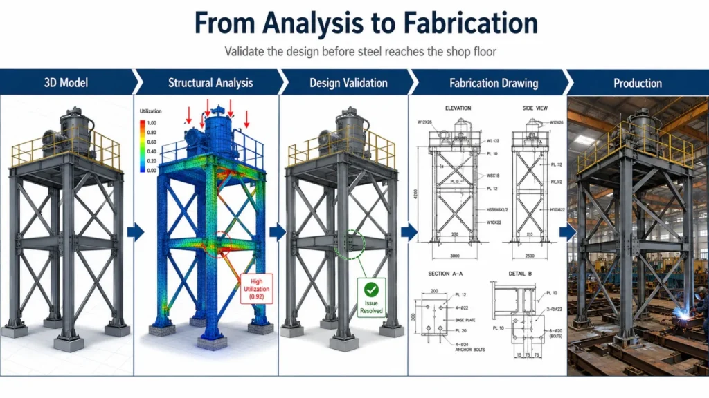
A reliable workflow can be organized into several stages.
Step 1: Define the Structural Requirements
Establish:
- Structural geometry
- Material grades
- Member types
- Support conditions
- Equipment loads
- Environmental loads
- Applicable design codes
- Serviceability requirements
- Connection requirements
The quality of the analysis depends heavily on the quality of its inputs.
Step 2: Build the Structural Model
Create the analytical model using appropriate structural elements such as:
- Beam elements
- Shell elements
- Plate elements
- Solid elements where required
The level of modeling detail should match the engineering objective.
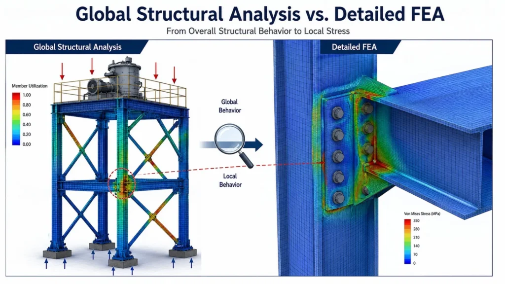
For a large steel frame, beam-based modeling may efficiently represent the global behavior. For localized components such as brackets, base plates, or complex connections, more detailed FEA may be appropriate.
Step 3: Apply Loads and Load Combinations
Loads should reflect realistic operating and environmental conditions.
Depending on the project, these may include:
- Dead load
- Live load
- Wind load
- Seismic load
- Equipment load
- Maintenance load
- Thermal load
- Dynamic or operational load
The applicable design code determines the required load combinations.
Step 4: Evaluate Structural Response
Review important analysis results including:
- Member utilization
- Stress
- Axial force
- Shear force
- Bending moment
- Displacement
- Reactions
- Buckling behavior
- Connection forces
Do not rely only on a single maximum stress value. Structural behavior should be evaluated across relevant load cases and critical members.
Step 5: Optimize the Design
If the analysis identifies an issue, revise the design before fabrication.
Possible modifications include:
- Changing beam sections
- Increasing plate thickness
- Adding stiffeners
- Modifying bracing
- Adjusting support locations
- Improving connections
- Reducing spans
- Changing material grades
- Revising structural geometry
The model can then be re-analyzed to verify the revised design.
Step 6: Release the Validated Design for Detailing
Once the structural design has been verified, the approved information can move into the detailing and fabrication drawing stage.
This creates a controlled transition between engineering analysis and manufacturing.
How FEA Supports Complex Steel Structure Analysis
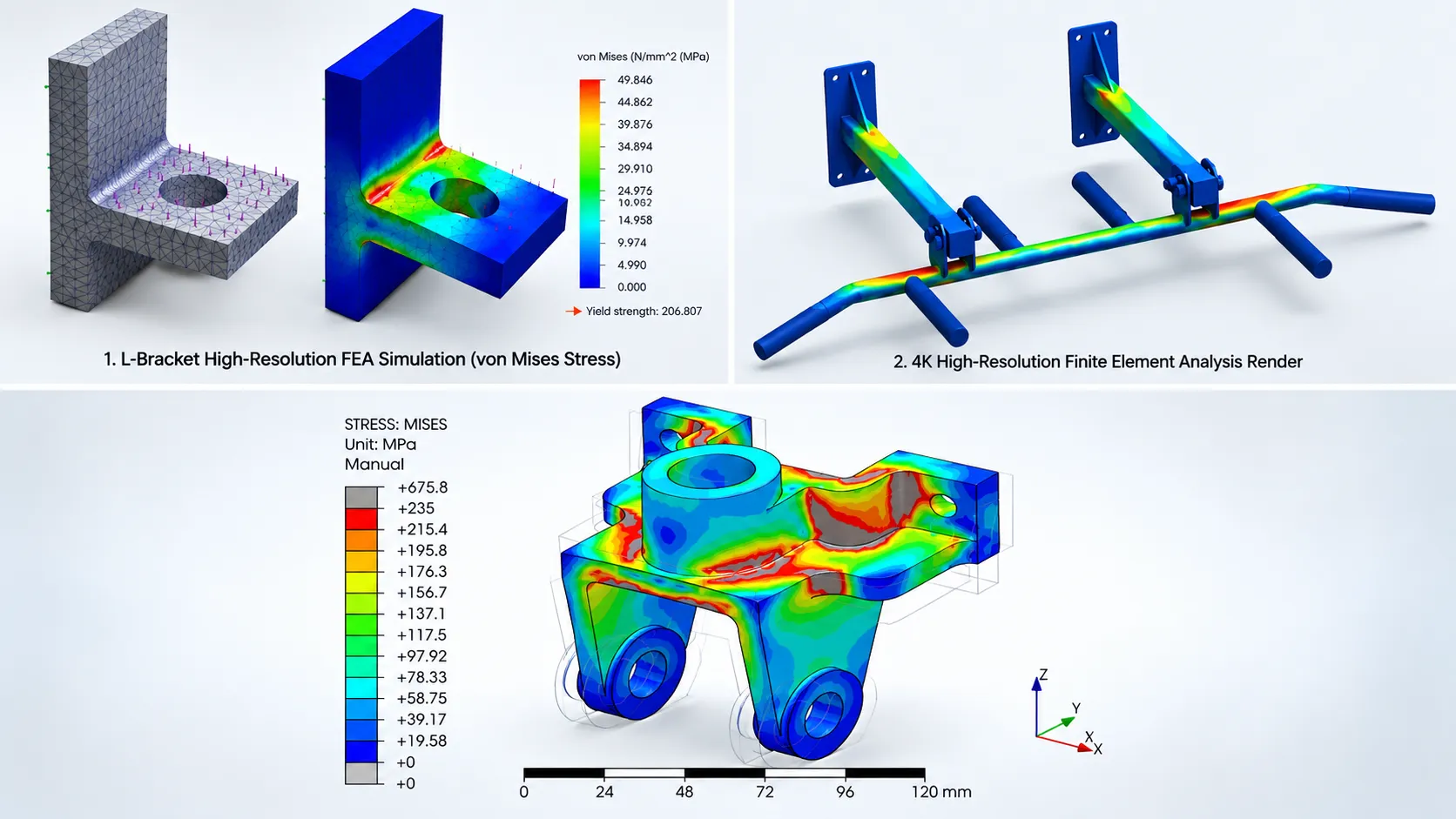
Finite Element Analysis (FEA) becomes especially useful when conventional structural calculations do not adequately represent a complex component or local behavior.
FEA can be used to investigate:
- Local stress concentrations
- Bracket behavior
- Base plates
- Gusset plates
- Welded assemblies
- Equipment supports
- Connection regions
- Irregular geometries
- Local deformation
- Contact behavior
For example, a steel equipment support may appear adequate when evaluated as part of a global frame model. However, a detailed FEA model of the bracket may reveal localized stress concentrations around bolt holes or welded regions.
This distinction is important:
Global structural analysis evaluates the behavior of the overall steel structure.
Detailed FEA evaluates localized structural behavior where additional detail is required.
Using the appropriate analysis method at each stage can improve design confidence without unnecessarily increasing modeling complexity.
Structural Analysis Reduces Cost by Moving Problem Detection Earlier
The cost of correcting a problem generally increases as a project moves closer to production and installation.
A simplified workflow looks like this:
Concept → Structural Analysis → Design Revision → Detailing → Fabrication → Assembly → Installation
A design modification during analysis may involve changing a digital model.
The same modification after fabrication may involve:
- Re-cutting steel
- Re-drilling holes
- Removing welds
- Replacing plates
- Reworking assemblies
- Re-inspecting components
- Delaying shipment
- Delaying installation
AISC guidance on fabrication errors similarly notes that some corrections can involve significant cutting, gouging, welding, or other corrective work, and that major deviations should be evaluated appropriately.
This is why early structural analysis is a form of risk reduction.
Integrating Structural Analysis With CAD and Detailing
The greatest benefit comes when analysis, CAD modeling, and detailing are treated as connected engineering activities.
A typical digital workflow can be:
3D CAD Model → Structural Analysis → Design Verification → Member & Connection Revision → Detailed 3D Model → Fabrication Drawings → BOM / Manufacturing Data → Steel Fabrication
This approach reduces the possibility of disconnected engineering information.
For fabrication-focused projects, the structural model and detailed CAD model should remain aligned with the approved design assumptions.
AISC guidance also highlights the importance of checking shop drawings and manufacturing models against project requirements before fabrication and erection.
What Should Be Checked Before Releasing a Steel Structure for Fabrication?
A pre-fabrication review should consider at least the following:
Structural Performance
- Member strength
- Deflection
- Buckling and stability
- Load combinations
- Support reactions
- Load paths
Connections
- Connection forces
- Bolt requirements
- Weld requirements
- Plate thickness
- Stiffeners
- Edge distances and spacing
Geometry
- Overall dimensions
- Member locations
- Elevations
- Bracing
- Equipment interfaces
- Clearances
Fabrication Readiness
- Member sizes
- Plate dimensions
- Cut requirements
- Hole locations
- Weld information
- Material specifications
- Piece marks
- Assembly information
Documentation
- Structural analysis report
- Design calculations
- Approved drawings
- Fabrication drawings
- BOM
- Revision control
This type of review helps establish a controlled path from engineering design to production.
Benefits of Structural Analysis Before Steel Fabrication
Using structural analysis before releasing a steel structure for fabrication can provide several practical benefits.
- Fewer Design-Related Errors: Potential structural problems can be identified before manufacturing begins.
- Reduced Rework: Design modifications are generally easier to make in the digital model than after components have been fabricated.
- Better Material Utilization: Analysis can help avoid both under-designed and unnecessarily heavy members.
- Improved Fabrication Coordination: Validated member sizes, loads, connections, and geometry provide better information for detailing.
- Greater Structural Confidence: Engineers can verify how the structure responds to defined load cases rather than relying only on assumptions.
- Better Communication: Analysis results can provide a technical basis for discussions between structural engineers, designers, detailers, fabricators, and project teams.
Structural Analysis Is More Than a Safety Check
Structural analysis is sometimes viewed simply as a process for determining whether a structure is “safe.”
In a modern steel fabrication workflow, its role is broader.
It helps answer important engineering questions:
- Will the members carry the expected loads?
- Where are the critical forces?
- Is the load path logical?
- Will the structure deform excessively?
- Are compression members stable?
- Are connection forces reasonable?
- Does the structural geometry work with surrounding equipment?
- Can the design be detailed and fabricated efficiently?
- Can potential problems be corrected before material reaches the shop floor?
These questions connect structural engineering with manufacturing.
How Immersiv Techsphere Supports Structural Engineering Workflows
At Immersiv Techsphere, structural engineering workflows can be supported through 3D modeling, structural analysis, detailed CAD development, and fabrication-oriented engineering documentation.
For steel structure projects, an integrated approach can help connect:
Structural Model → Analysis → 3D CAD → Detailing → Fabrication Drawings
This approach is particularly valuable for industrial structures, equipment support structures, platforms, frames, and fabrication-focused projects where structural performance and manufacturing accuracy need to work together.
The goal is not simply to produce an analysis report. The objective is to help create engineering information that can move reliably from design to fabrication.
Frequently Asked Questions
Structural analysis is the process of evaluating how a steel structure responds to applied loads. It helps determine member forces, stresses, deflections, reactions, stability, and other structural responses required to validate the design.
Structural analysis can help prevent design-related fabrication problems by identifying issues such as incorrect member sizes, inadequate load paths, excessive deflection, stability concerns, and connection forces before fabrication begins. It cannot eliminate shop-floor fabrication mistakes such as incorrect cutting or drilling.
Performing structural analysis before fabrication allows engineers to identify and correct design problems while changes can still be made digitally. This can reduce material waste, rework, fabrication delays, and downstream coordination issues.
FEA can evaluate detailed structural behavior such as stress distribution, deformation, local stress concentrations, buckling, contact behavior, and complex load transfer. It is particularly useful for components and regions where simplified structural models may not provide sufficient detail.
Common issues include overstressed members, excessive deflection, inadequate bracing, buckling risks, high support reactions, unexpected load paths, and connection forces that require design changes.
No. FEA is one numerical method used for structural analysis. Structural analysis can include analytical calculations, beam and frame analysis, finite element analysis, stability analysis, and other engineering methods depending on the project.
Structural analysis should be performed during the engineering design stage and before final fabrication information is released. Iterative analysis is often required when the structural design changes.
Conclusion
Structural analysis is one of the most effective opportunities to identify steel structure problems before they become fabrication problems.
By evaluating member capacity, load paths, deflection, stability, connections, reactions, and structural geometry before production, engineering teams can make informed design changes while the project is still in the digital stage.
The key workflow is straightforward:
Analyze → Validate → Optimize → Detail → Fabricate
AISC’s fabrication and detailing guidance reinforces the importance of controlling design information, checking drawings and models, and addressing fabrication deviations appropriately.
For steel fabricators, structural engineers, mechanical design teams, and industrial equipment manufacturers, this early validation can reduce rework, improve coordination, and create a more reliable transition from engineering design to production.
The earlier a structural problem is identified, the easier and less expensive it is to correct.
Have a Project in Mind?
Need help with 3D animation, industrial visualization, HSE training animation, or product visualization? Tell us about your project and our team will get back to you.