
Table of Contents
A Case Study on Visualizing Complex Equipment Installation Before It Reaches the Site
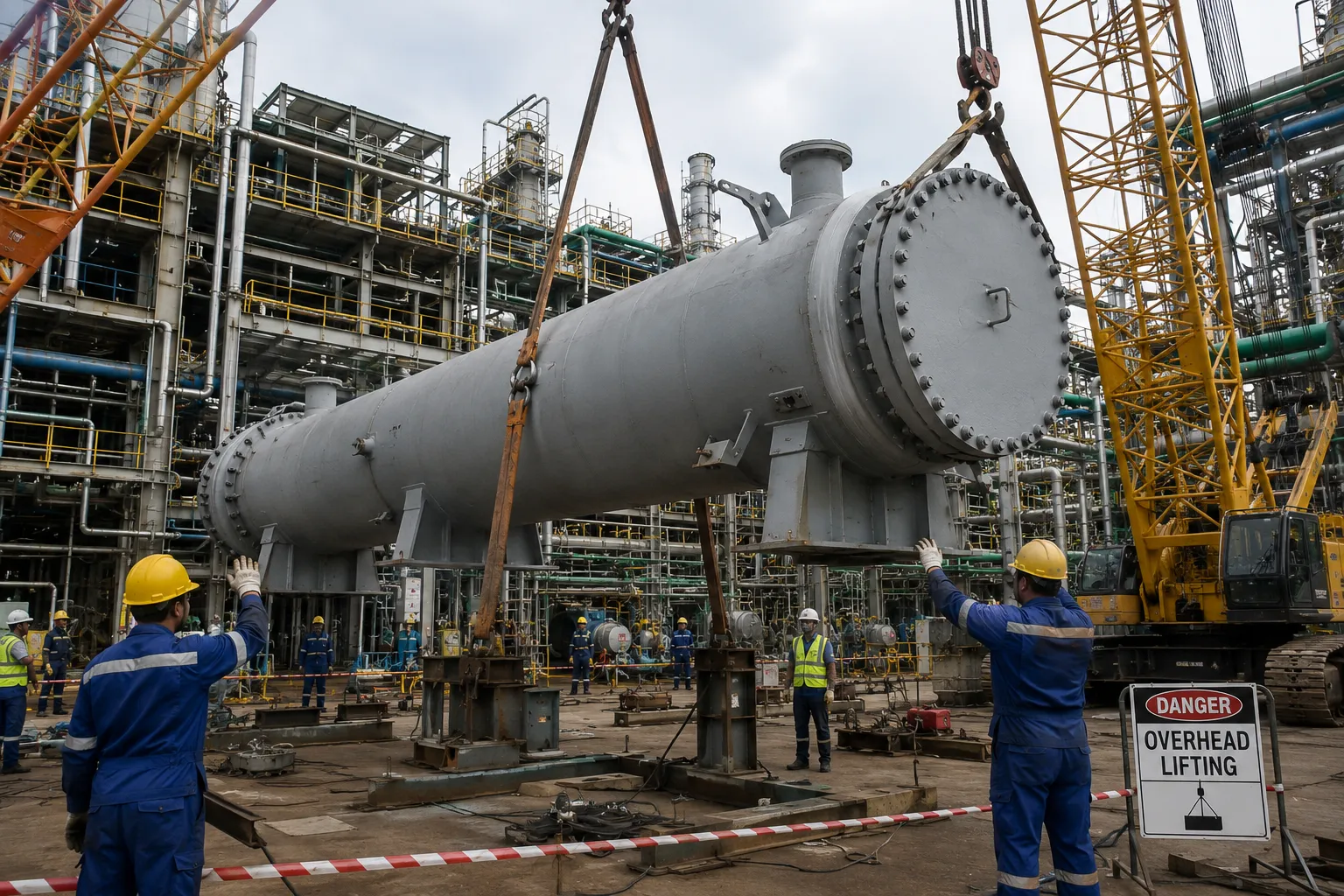
Installing heavy industrial equipment is not simply a matter of moving components from a fabrication shop to a project site and bolting them together.
For equipment such as shell-and-tube heat exchangers, economizers, industrial boilers, pressure vessels, and large process skids, installation involves a carefully coordinated sequence of lifting, positioning, alignment, access, fastening, welding, and final integration.
A small error in this sequence can create significant consequences.
A component installed in the wrong orientation may interfere with adjacent piping. A structural member fixed too early may block welding access. An incorrect lifting sequence can require equipment to be removed and repositioned. When heavy-lift cranes, specialized rigging teams, welders, and multiple subcontractors are involved, even a short delay can quickly increase project costs.
This case study demonstrates how a 3D assembly animation developed by Immersiv Techsphere helped transform complex engineering information into a clear, step-by-step installation sequence that could be reviewed before equipment reached the site.
Project Overview
The project involved developing a visual assembly sequence for complex heavy industrial equipment consisting of multiple interconnected components and structural elements.
The available project data included:
- 3D CAD models
- General arrangement drawings
- Fabrication drawings
- Assembly drawings
- Orthographic views
- Cross-sections
- Technical installation information
While these documents provided the required engineering details, the installation process itself was difficult to communicate through static drawings alone.
The final assembly was clearly defined, but understanding how the equipment needed to be assembled step by step required site personnel to interpret multiple drawings and mentally visualize the movement of large components.
The project therefore required a clearer and more accessible way to communicate the complete installation sequence.
The Challenge: Translating 2D and 3D Engineering Data into a Clear Installation Process
Heavy industrial equipment installation involves several dependencies that are not always immediately apparent when reviewing a final CAD model or a set of fabrication drawings.
The project team faced three key challenges.
1. Understanding Component Orientation and Movement
Large industrial components often need to approach their final position from a specific direction.
A shell section, cover, support, nozzle assembly, or structural component may require rotation or controlled movement before it can be correctly positioned.
Static drawings can show the final location of these components, but they do not always clearly communicate:
- How the component moves into position
- The correct installation direction
- The orientation during assembly
- The relationship between moving and already installed components
This increased the possibility of different team members interpreting the installation process differently.
2. Managing the Correct Assembly Sequence
The correct final configuration does not necessarily indicate the correct installation order.
A component installed too early could restrict access to another operation. For example, a structural member or enclosure section could potentially limit access to:
- Internal welding locations
- Bolted connections
- Tie rods
- Inspection points
- Torqueing operations
The project team needed to evaluate the assembly as a sequence of physical operations rather than simply reviewing the completed equipment model.
3. Identifying Potential Installation Conflicts
Large components can interact with surrounding structural steel, piping, supports, and adjacent equipment during installation.
Potential issues included:
- Insufficient clearance for positioning
- Interference with nearby structural members
- Component fouling during movement
- Obstruction caused by previously installed assemblies
- Incorrect installation direction
Identifying such issues after equipment and lifting resources are mobilized can result in additional coordination, repositioning, and avoidable rework.
The challenge was to identify and communicate these concerns earlier in the planning process.
The Problem on Site: When 2D Drawings Meet Real-World Constraints
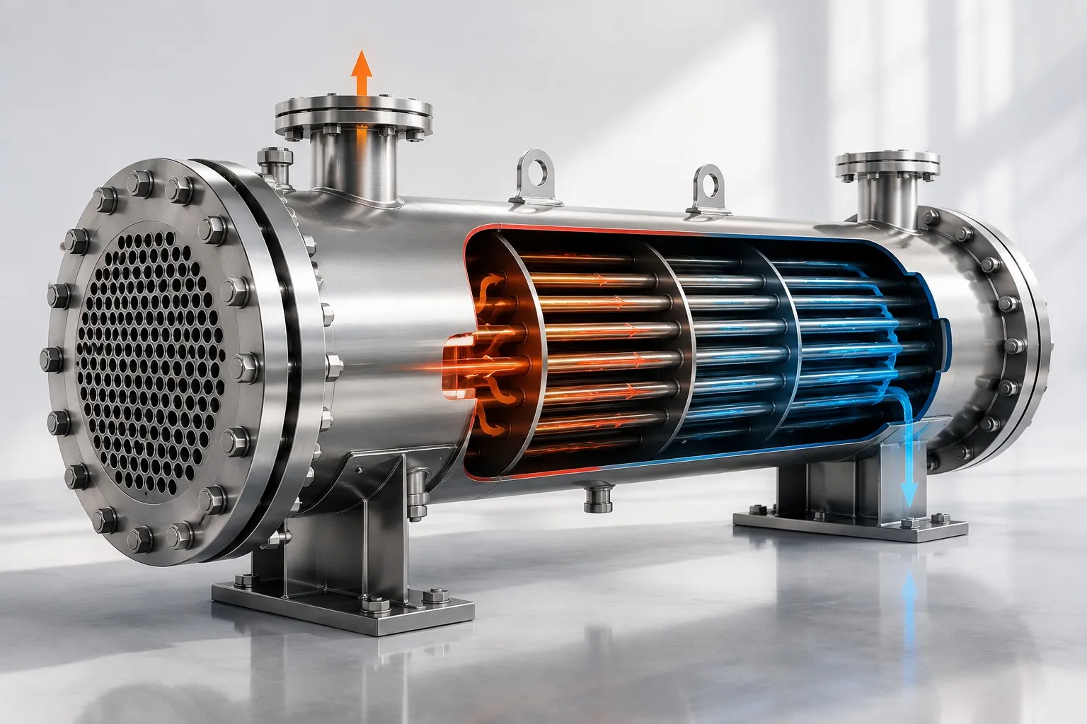
A typical example involved a large shell-and-tube heat exchanger assembly with multiple internal and external components, including tube sheets, internal assemblies, shell sections, covers, structural supports, and external nozzle connections.
During installation planning, several potential issues had to be considered.
- Spatial Misinterpretation: A 2D drawing can accurately define dimensions and component locations, but it does not easily communicate how a large component moves through three-dimensional space. A multi-ton assembly may need to rotate, translate, or approach from a specific direction before reaching its final position. Without visualizing this movement, there is a risk that the component may interfere with nearby structural steel, external nozzles may foul against piping or supports, the required clearance for lifting and positioning may be underestimated, and the planned installation direction may not be physically possible.
- Incorrect Component Orientation: Certain industrial components must be positioned with a precise orientation. A support bracket, nozzle, cover, or structural connection installed incorrectly can create a clash with another system. Correcting this after installation may require disconnecting or removing the component, repositioning heavy lifting equipment, reinstalling the component, and rechecking alignment and connections. For heavy industrial equipment, this type of rework can consume valuable crane and labour time.
- Sequencing and Access Problems: Another challenge was installation order. A component may technically fit into its final location but still prevent the next task from being completed. For example, installing an outer structural member too early could block access to internal weld locations, bolted connections, tie rods, inspection points, torqueing operations, and maintenance access. The final assembly may appear correct in a CAD model while the actual installation sequence remains impractical.
Solution Provided: 3D Assembly Animation and Digital Installation Sequencing
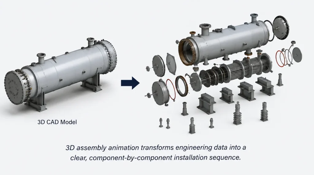
Immersiv Techsphere developed a detailed 3D assembly animation based on the available engineering and CAD data.
The objective was not simply to create a visually appealing animation.
The animation was developed as a visual installation planning tool.
Each major component and sub-assembly was organized according to its actual installation sequence.
The process involved transforming the static equipment model into a step-by-step assembly simulation.
Step 1: Understanding the Equipment and Assembly Logic
The technical team first reviewed the available CAD models and engineering information to understand:
- Equipment configuration
- Major and minor sub-assemblies
- Component interfaces
- Installation dependencies
- Potential access constraints
- Final assembly relationships
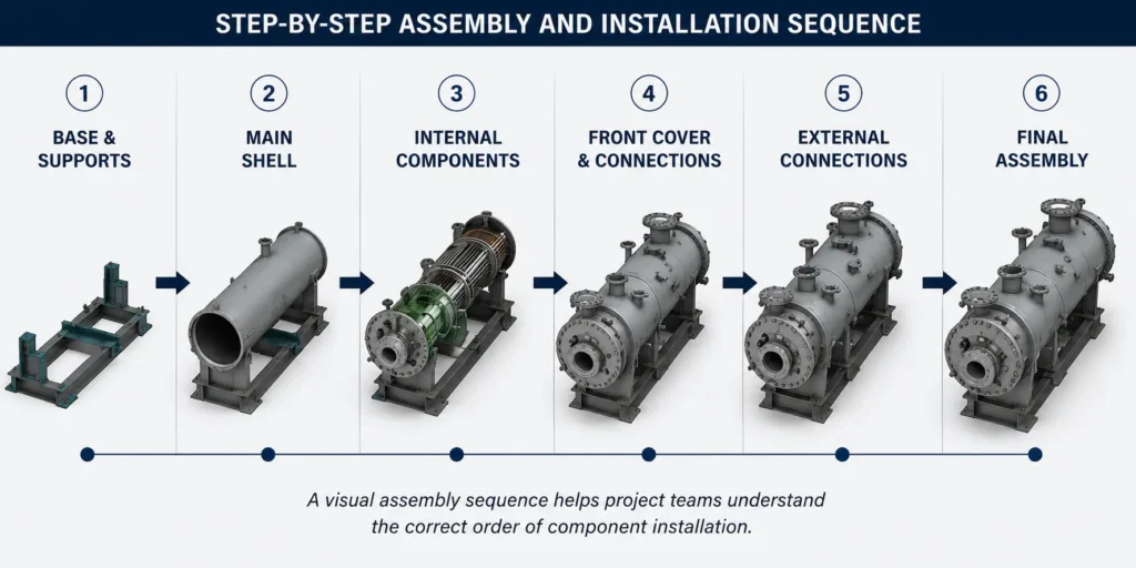
The equipment was then divided into logical installation stages.
This allowed the complete assembly process to be reviewed as a sequence rather than as a single finished model.
Step 2: Creating the Component-by-Component Assembly Sequence
Each major component was animated individually according to the planned installation process.
The sequence demonstrated:
- Where each component originated
- How it moved into position
- Its installation direction
- Its orientation
- Its relationship with surrounding components
- The order in which connections were completed
Instead of asking site personnel to interpret multiple drawings simultaneously, the animation provided a clear visual answer to a simple question:
What happens next?
This made the installation logic easier to review for engineers, supervisors, operators, and site crews.
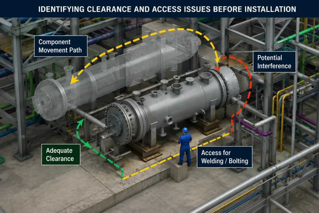
Step 3: Identifying Potential Component Interference
As the assembly sequence was developed, the movement of each component was reviewed against surrounding equipment and structural elements.
This helped identify potential conflicts during the digital planning stage.
For example, the team could examine whether:
- A shell section had sufficient clearance during positioning.
- A nozzle would interfere with an adjacent support.
- A structural bracket created an obstruction.
- A component required a different installation direction.
- Two components could occupy the same space during assembly.
When a potential clash was identified, it could be reviewed with the engineering team before the physical installation process began.
The sequence could then be revised digitally instead of discovering the issue after equipment arrived on site.
Step 4: Reviewing Installation Accessibility
The animation also helped evaluate access requirements during assembly.
This was particularly important for operations such as:
- Welding
- Bolting
- Torqueing
- Inspection
- Internal connections
- Alignment checks
The team reviewed whether an installation step unintentionally blocked the next activity.
For example, if an enclosure panel or structural member was installed too early, it could restrict access to an internal connection.
By changing the sequence in the animation, the project team could identify a more practical installation order.
The focus was not only on whether components could fit together, but also on whether personnel could realistically complete the required work between installation stages.
Before and After: From Static Drawings to a Clear Installation Sequence
Before 3D Assembly Animation: The installation team relied primarily on multiple engineering documents.
The process required personnel to:
- Review several drawing sheets.
- Interpret different views and cross-sections.
- Visualize component movement mentally.
- Coordinate installation order through discussions.
- Identify access issues during planning or on site.
Different stakeholders could interpret the same assembly information differently. A visual assembly sequence can provide a clearer and more consistent way to communicate complex installation procedures compared with traditional demonstrations and static documentation.
After 3D Assembly Animation: The complete sequence was visualized as a continuous installation process.
The animation showed:
- The starting position of each component.
- The direction of movement.
- The installation order.
- Component orientation.
- Assembly relationships.
- Critical connection stages.
- Final equipment configuration.
The project team could review the installation sequence collectively before execution.
This created a common visual reference for engineers, supervisors, rigging teams, and installation personnel.
Impact: Reducing Installation Uncertainty Before Site Execution
The 3D Assembly Animation provided a clearer way to communicate the installation process before physical assembly began.
Clearer Understanding of Installation Steps
The complete assembly process could be viewed as a logical sequence instead of being interpreted from multiple independent drawings.
This helped project teams understand how individual components progressed toward the final equipment configuration.
1. Improved Installation Clarity
Complex engineering information was converted into a format that could be understood quickly.
Instead of interpreting multiple orthographic and sectional views, the installation team could watch the complete assembly process in sequence.
This reduced ambiguity around:
- Component orientation
- Installation direction
- Assembly dependencies
- Sequence of operations
2. Earlier Identification of Potential Clashes
The digital assembly sequence created an opportunity to identify potential interference before installation.
This allowed engineering teams to review and modify:
- Component positioning
- Installation direction
- Assembly order
- Structural interfaces
Addressing these issues during planning is significantly easier than resolving them after heavy equipment has been mobilized.
3. Better Coordination Between Engineering and Site Teams
Engineering teams often understand the equipment design in detail, while site teams understand the practical realities of installation.
The 3D animation provided a common communication medium between these groups.
Rather than discussing a component using drawing numbers and sectional references, the team could review the exact installation step visually.
This made technical discussions more focused and easier to communicate across multiple stakeholders.
4. Reduced Risk of Rework
Rework in heavy industrial projects can involve significant resources.
An incorrectly installed component may require:
- Additional lifting operations
- Equipment repositioning
- Labour hours
- Welding or re-fabrication
- Project schedule adjustments
By reviewing the installation sequence digitally, potential issues could be addressed earlier in the project lifecycle.
5. More Effective Training and Site Briefing
The animation could also be used as a visual reference during:
- Pre-installation meetings
- Toolbox talks
- Contractor coordination
- Installation training
- Client presentations
New team members could quickly understand the overall assembly process without reviewing the entire engineering drawing package.
Results at a Glance
The 3D Assembly Animation helped the project team:
- Visualize the complete equipment installation sequence
- Clearly communicate component movement and orientation
- Review the relationship between installation stages
- Discuss potential clearance and interference concerns
- Evaluate accessibility during assembly
- Improve coordination between engineering and site teams
- Reduce uncertainty before physical installation
Key Takeaway: The CAD Model Should Not Stop at Design
A detailed 3D CAD model contains valuable engineering information, but its value does not have to end with design and fabrication.
The same model can be transformed into a visual installation sequence that helps project teams understand how equipment moves from individual components to a fully assembled system.
For complex industrial equipment, 3D assembly animation can act as a bridge between engineering intent and site execution.
It helps answer critical questions before installation begins:
- What is the correct assembly sequence?
- Which component should be installed first?
- How will large components move into position?
- Are there potential clashes during installation?
- Will technicians have sufficient access to complete their work?
- Does the planned sequence create unnecessary rework risks?
By identifying these issues during the digital planning stage, project teams can reduce uncertainty before cranes, equipment, and installation crews are mobilized.
How Immersiv Techsphere Supports Industrial Installation Planning
Immersiv Techsphere develops 3D assembly animations and industrial equipment animations that help engineering, manufacturing, and project teams communicate complex processes visually. These technical and industrial animation services can help transform complex engineering information into clear visual content for installation, training, operations, and project communication.
Using existing 3D CAD models, drawings, and engineering data, we can create detailed animations for:
- Heavy equipment assembly
- Installation sequencing
- Equipment erection
- Process equipment animation
- Maintenance procedures
- Operating sequences
- Technical training
- Client and stakeholder presentations
The goal is not only to show how equipment looks.
It is to make complex engineering processes easier to understand, review, and communicate before work begins.
For large industrial projects where installation errors can result in delays, rework, and coordination challenges, a detailed 3D assembly animation provides a practical way to visualize the process before execution begins.
Frequently Asked Questions
3D assembly animation visually shows how individual components move, fit together, and form a complete industrial equipment assembly.
It helps teams review component orientation, installation sequence, and potential conflicts before physical installation begins.
Yes. Existing 3D CAD models, assembly drawings, and technical information can be used to develop the animation.
It can be used for heat exchangers, pressure vessels, boilers, process skids, structural assemblies, and other complex industrial equipment.
Yes. Visualizing component movement and installation sequences can help identify potential interference and clearance issues.
Yes. It provides a clear visual reference for installation teams, contractors, and technicians to understand the correct assembly process.
Engineers, project managers, fabrication teams, installation crews, contractors, and clients can all use it for better technical communication.
A product animation focuses on appearance or features, while an assembly animation demonstrates how components are assembled or installed.
Conclusion
This case study demonstrates how 3D Assembly Animation can help bridge the gap between engineering information and site execution.
By converting existing CAD models and technical data into a clear component-by-component sequence, Immersiv Techsphere helped make a complex installation process easier to understand and communicate.
The animation provided a visual reference for reviewing component movement, orientation, assembly order, accessibility, and potential installation concerns before physical work progressed.
For heavy industrial equipment involving complex assemblies and multiple installation stages, 3D Assembly Animation provides an effective way to communicate the intended process and improve clarity across engineering and installation teams.