

Table of Contents
Introduction
Sheet metal components are used across industrial equipment, machinery, electrical enclosures, automotive systems, HVAC products, consumer products, and many other manufacturing applications. While modern CAD software makes it relatively easy to create complex sheet metal models, not every design can be manufactured efficiently.
For projects that require production-ready sheet metal design, engineers can also benefit from specialized sheet metal design services that account for fabrication and manufacturing requirements.
A part may look correct in a 3D CAD model but still create unnecessary tooling complexity, require additional manufacturing operations, increase material waste, or lead to dimensional issues during bending and assembly.
This is where Design for Manufacturing (DFM) becomes important. Sheet metal DFM involves designing components with manufacturing processes in mind from the beginning. By considering material properties, bend geometry, hole placement, tolerances, tooling, and assembly requirements during the design stage, manufacturers can reduce production challenges and improve overall efficiency.
This article explains the key sheet metal DFM guidelines engineers and product designers should consider when designing parts for efficient manufacturing.
What Is Sheet Metal DFM?
Sheet Metal Design for Manufacturing (DFM) is the practice of designing sheet metal parts so they can be manufactured reliably, efficiently, and cost-effectively.
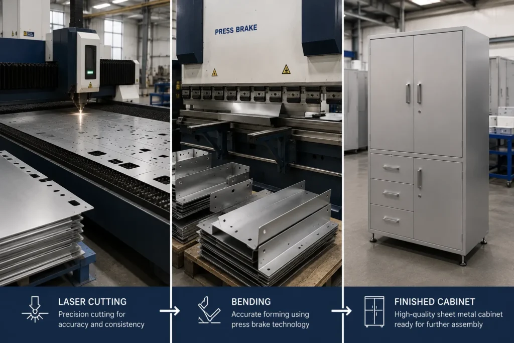
A typical sheet metal manufacturing workflow may involve:
- Cutting the flat pattern
- Punching or laser cutting features
- Forming bends
- Adding secondary operations
- Welding or fastening components
- Applying surface finishes
- Inspecting the final part
The design decisions made in CAD directly affect each of these stages.
For example, a hole placed too close to a bend may deform during forming. Extremely tight tolerances may require additional inspection or specialized manufacturing processes. Complex bend sequences may increase setup time and reduce production efficiency.
By applying DFM principles for sheet metal, engineers can identify and avoid these issues before production begins.
Why Is DFM Important in Sheet Metal Design?
The cost of modifying a sheet metal component generally increases as the design moves further into the manufacturing process.
A design issue identified during CAD modeling may only require a quick model update. The same issue discovered after tooling, fabrication, or assembly can result in rework, production delays, and additional costs.
Effective sheet metal DFM can help manufacturers:
- Reduce manufacturing complexity
- Minimize material waste
- Reduce the number of production operations
- Improve part consistency
- Simplify tooling and setup
- Reduce rework
- Improve assembly efficiency
- Shorten product development cycles
The goal is not simply to make a part easier to manufacture. Good DFM creates a balance between design requirements, functional performance, manufacturability, and production cost.
1. Select the Right Sheet Metal Material and Thickness
Material selection is one of the first decisions that affects manufacturability.
Different materials behave differently during cutting, bending, welding, and finishing. Common sheet metal materials include:
- Mild steel
- Stainless steel
- Aluminum
- Galvanized steel
- Copper and copper alloys
The selected material should meet both functional and manufacturing requirements.
Important factors include:
- Required strength
- Corrosion resistance
- Weight
- Formability
- Weldability
- Surface finish requirements
- Material availability
- Production cost
Keep Thicknesses Standard Where Possible
Using standard material thicknesses can simplify sourcing and manufacturing.
Unnecessarily unique or non-standard thicknesses may increase material procurement complexity and cost. When multiple parts are used within the same product, standardizing sheet thicknesses where practical can also simplify inventory management and production planning.
The material thickness should also be considered when designing bends, holes, slots, and formed features.
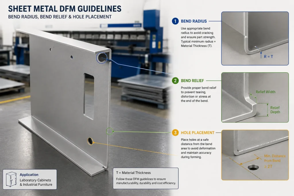
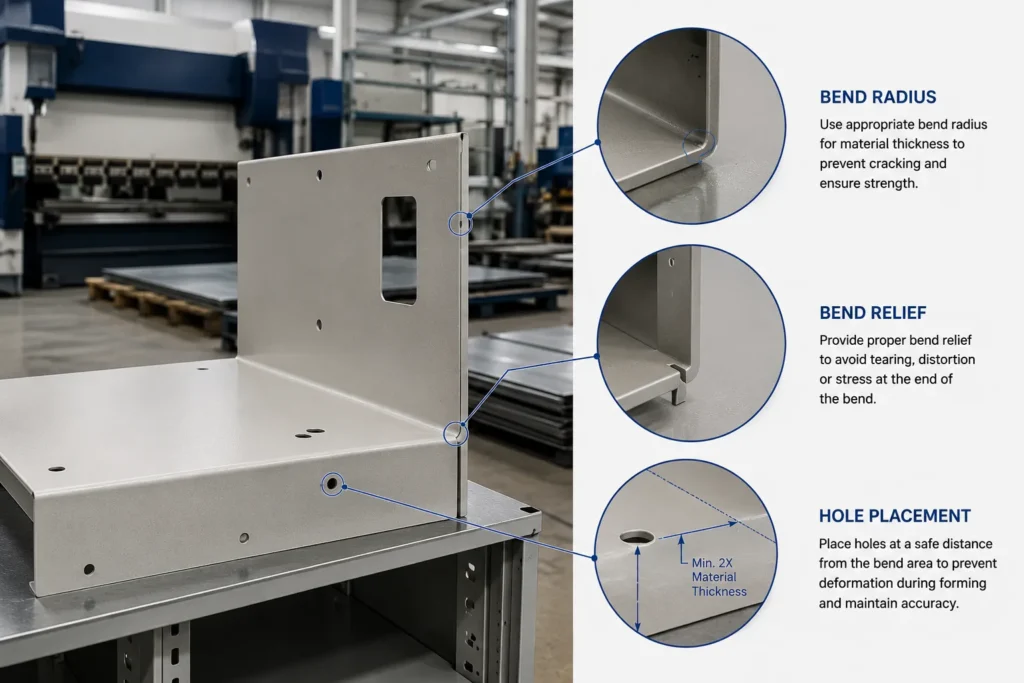
2. Use Appropriate Bend Radius
The bend radius is one of the most important parameters in sheet metal design.
A bend radius that is too small for the selected material can create excessive stress and increase the risk of cracking. A very large radius, on the other hand, may affect the part’s functional geometry or require different tooling.
As a general DFM principle, designers should:
- Use bend radii appropriate for the material and thickness
- Maintain consistency where possible
- Avoid unnecessary variations in bend radius
- Consider the grain direction of the material when designing critical bends
Standardizing bend radii across a component can reduce tooling changes and simplify the bending process.
However, the exact minimum bend radius depends on factors such as material type, temper, thickness, and manufacturing method. Therefore, designers should confirm bend requirements with the manufacturing team or fabricator.
3. Maintain Consistent Bend Orientation
Parts with numerous bends can become difficult to manufacture when bend directions and sequences are unnecessarily complex.
Whenever possible, designers should simplify the forming sequence and avoid geometries that require the part to be repeatedly repositioned.
A simpler bend strategy can help reduce:
- Press brake setups
- Part handling
- Manufacturing time
- Operator intervention
- Opportunities for dimensional variation
When designing complex enclosures, brackets, frames, or covers, it is useful to consider how the part will physically move through the bending process rather than focusing only on the final 3D geometry.
4. Keep Holes and Cutouts Away From Bend Areas
Holes, slots, and other cut features placed too close to a bend can deform during the forming process.
When sheet metal bends, the surrounding material experiences stretching and compression. Features located within or too close to this deformation zone may become distorted.
Potential problems include:
- Oval or distorted holes
- Changes in feature dimensions
- Cracking near the cutout
- Reduced dimensional accuracy
As a general guideline, holes and cutouts should be positioned a sufficient distance away from bend lines based on the material thickness, bend radius, and manufacturing process.
If a feature must be located close to a bend, designers should review the geometry with the fabricator and determine whether a relief feature, alternative forming sequence, or secondary machining operation is required.
5. Use Proper Bend Reliefs
Bend reliefs are small features added near the end of a bend to prevent material tearing, deformation, or unwanted stress concentration.
Without sufficient relief, the material near a bend intersection may:
- Crack
- Stretch excessively
- Distort adjacent features
- Create inconsistent edge geometry
Common bend relief designs include rectangular, rounded, and tear-drop style reliefs.
The appropriate relief geometry depends on the material thickness, bend radius, and manufacturing method.
Adding bend reliefs during the CAD design stage can improve both manufacturability and part consistency.
6. Avoid Unnecessarily Complex Geometries
Complex geometry does not always mean better functionality.
Features such as extremely narrow sections, intricate cut patterns, sharp internal corners, and difficult-to-access bends can increase manufacturing time and cost.
When reviewing a sheet metal part, engineers should ask:
- Is every feature necessary?
- Can multiple features be simplified into one?
- Can a complex profile be replaced with a standard geometry?
- Does the design require unnecessary secondary operations?
- Can the number of bends be reduced?
Simplifying the design can reduce programming time for CNC cutting, improve nesting efficiency, simplify forming, and reduce overall production complexity.
7. Design Holes, Slots, and Features for Manufacturing Tools
Small features can be difficult or inefficient to manufacture depending on the selected process.
For example, extremely small holes may require specialized punching or machining operations. Narrow slots may also be difficult to cut accurately or may create weak sections in the material.
When designing holes and slots, consider:
- Material thickness
- Minimum feature size
- Tool availability
- Cutting method
- Required tolerances
- Feature accessibility
Standardizing common hole diameters can also simplify tooling and reduce manufacturing complexity.
For threaded holes, engineers should also determine whether the material thickness is sufficient for direct threading or whether alternative features such as PEM inserts, nuts, or threaded bosses are more suitable.
8. Minimize the Number of Bends
Each bend can add manufacturing time and introduce another source of dimensional variation.
While bends are essential to creating functional sheet metal components, unnecessary bends should be avoided.
Reducing the number of bends can provide several benefits:
- Faster production
- Fewer press brake operations
- Reduced setup requirements
- Lower manufacturing cost
- Improved dimensional consistency
During DFM reviews, designers should evaluate whether a particular bend contributes to the structural or functional purpose of the part.
If not, the feature may be a candidate for simplification.
9. Consider Flat Pattern Development and Bend Allowance
A sheet metal part must eventually be converted into a flat pattern for cutting.
The relationship between the flat pattern and the final formed geometry depends on factors such as:
- Material thickness
- Bend radius
- Bend angle
- Material properties
- K-factor or bend allowance
Incorrect bend allowance values can result in formed parts that do not achieve the required final dimensions.
This makes accurate sheet metal CAD modeling important.
Modern CAD software allows engineers to define material properties, bend parameters, and sheet metal rules so that the 3D model and flat pattern remain associated.
A parametric approach also makes it easier to update the design when material thickness, bend radius, or feature dimensions change.
10. Avoid Extremely Tight Tolerances Unless Necessary
Tighter tolerances generally increase manufacturing and inspection requirements.
Not every feature on a sheet metal component requires the same level of dimensional accuracy.
Designers should identify:
- Critical functional dimensions
- Assembly interfaces
- Clearance requirements
- Non-critical dimensions
Tight tolerances should be applied primarily where they are necessary for product performance or assembly.
Over-tolerancing can increase:
- Manufacturing time
- Inspection requirements
- Scrap rates
- Production costs
A practical tolerance strategy helps manufacturers focus precision where it delivers actual functional value.
11. Consider Welding and Assembly Requirements Early
Many sheet metal products consist of multiple components that must be joined through:
- Welding
- Riveting
- Fasteners
- Clinching
- Self-clinching hardware
- Adhesive bonding
The design should provide sufficient access for the required assembly process.
For welded assemblies, consider:
- Access for welding tools
- Weld joint design
- Heat distortion
- Fixture requirements
- Post-weld finishing
For mechanically fastened assemblies, consider tool access, fastener clearance, and assembly sequence.
A component that is individually easy to manufacture may still create problems if the overall assembly process is not considered.
12. Reduce Secondary Operations
Secondary operations can add significant production time and cost.
Examples include:
- Additional machining
- Deburring
- Manual finishing
- Drilling after forming
- Repositioning for multiple operations
Whenever possible, designers should evaluate whether features can be incorporated into the primary cutting or forming process.
For example, combining compatible features into the initial laser cutting or punching operation may reduce the need for additional manufacturing steps.
The objective should be to create a production workflow with the minimum number of operations required to achieve the desired part function and quality.
13. Consider Material Grain Direction
Material grain direction can affect bending performance, particularly when working with certain materials or when tight bend radii are involved.
Bending across or parallel to the grain can produce different results depending on the material and forming conditions.
For critical components, grain direction should be considered during:
- Flat pattern orientation
- Material nesting
- Bend design
- Crack prevention
This is especially important for materials that are more susceptible to cracking during forming.
14. Design for Efficient Nesting and Material Utilization
The flat pattern layout has a direct impact on material utilization.
Parts with inefficient shapes may produce excessive scrap during cutting. Although nesting is often handled by CAM software, design decisions can still influence how efficiently parts fit within standard sheet sizes.
Designers should consider:
- Standard sheet dimensions
- Part orientation
- Repeated part shapes
- Material utilization
- Scrap generation
Small design changes may improve nesting efficiency and reduce material waste, particularly in high-volume production.
15. Use Standard Features and Hardware Where Possible
Custom features may increase manufacturing complexity.
Using standard components such as fasteners, inserts, and hardware can simplify sourcing and assembly.
Standardization can also provide advantages in:
- Inventory management
- Replacement parts
- Assembly tooling
- Procurement
- Production consistency
This does not mean every design should be limited to standard geometry. Instead, custom features should be used where they provide a clear functional advantage.
16. Review Tool and Machine Accessibility
A feature may be theoretically manufacturable but difficult to access with the required machine or tool.
For example:
- Deep narrow bends may limit press brake access.
- Internal features may be difficult to weld.
- Certain geometries may interfere with bending tools.
- Formed flanges may restrict subsequent operations.
A manufacturability review should consider the physical movement of the part and the accessibility of tools throughout the manufacturing process.
This is one of the areas where collaboration between design engineers and manufacturing teams becomes particularly important.
17. Use CAD and Automation to Improve Sheet Metal DFM
Modern CAD systems can help engineers identify and manage manufacturing requirements during the design process.
A parametric sheet metal model allows designers to control:
- Material thickness
- Bend radius
- Feature dimensions
- Hole patterns
- Flange lengths
- Flat pattern development
When design changes occur, the model can update based on defined relationships and parameters.
For organizations handling large numbers of similar sheet metal parts, CAD automation and product configurator solutions can further improve design efficiency by standardizing common options and reducing repetitive engineering work.
Automation can help standardize repetitive tasks such as:
- Creating sheet metal features
- Applying design rules
- Generating flat patterns
- Exporting DXF files
- Creating manufacturing drawings
- Checking naming and documentation requirements
By combining parametric CAD modeling, automation, and DFM practices, engineering teams can create a more consistent workflow from design to manufacturing.
Sheet Metal DFM Checklist
Before releasing a sheet metal design for manufacturing, engineers should review the following:
- Is the selected material appropriate for the application and manufacturing process?
- Is the material thickness standard and readily available?
- Are bend radii suitable for the material and thickness?
- Are bend directions and sequences practical?
- Are holes and cutouts sufficiently clear of bend areas?
- Are bend reliefs required at critical locations?
- Can the number of bends be reduced?
- Are minimum feature sizes suitable for the selected manufacturing process?
- Are tolerances applied only where functionally necessary?
- Does the flat pattern accurately account for bend allowance?
- Is the design suitable for efficient material nesting?
- Are welding and assembly operations accessible?
- Can secondary operations be reduced or eliminated?
- Are standard hardware and components being used where practical?
- Has the design been reviewed with the manufacturing team?
How Immersiv Techsphere Supports Sheet Metal Design and Engineering Automation
Efficient manufacturing starts with efficient engineering workflows.
Immersiv Techsphere helps engineering and manufacturing organizations improve their CAD processes through engineering automation, CAD customization, parametric modeling, and design workflow optimization.
Automation can help standardize repetitive engineering activities and reduce the manual effort involved in preparing designs and manufacturing data. For SolidWorks users, SolidWorks API and VBA automation can be used to automate repetitive modeling and documentation tasks within the CAD workflow.
Depending on the workflow, engineering automation can support activities such as:
- Automating repetitive CAD modeling tasks
- Standardizing sheet metal design processes
- Automating flat pattern and DXF generation
- Creating engineering documentation
- Developing custom CAD tools and workflows
- Reducing repetitive manual operations
- Improving design consistency across projects
By connecting engineering knowledge with automation, manufacturers can create more efficient and repeatable design-to-manufacturing workflows.
FAQs
DFM, or Design for Manufacturing, is the practice of designing sheet metal parts with manufacturing processes, material behavior, tooling, forming, tolerances, and assembly requirements in mind. The goal is to create parts that can be manufactured efficiently and consistently.
Key guidelines include selecting the right material and thickness, using appropriate bend radii, keeping holes away from bend areas, adding bend reliefs where required, minimizing unnecessary bends, avoiding overly tight tolerances, and considering assembly and tooling access.
Material deformation occurs around the bend area during forming. Holes or cutouts placed too close to a bend may become distorted or affect the dimensional accuracy of the finished part.
Parametric modeling allows engineers to define relationships between dimensions, material thickness, bends, and features. When a design parameter changes, related geometry can update automatically, making design changes faster and more consistent.
Yes. CAD automation can reduce repetitive work by automating tasks such as feature creation, flat pattern generation, DXF export, drawing creation, and other engineering documentation processes.
Immersiv Techsphere develops engineering automation and CAD customization solutions that can help manufacturers automate repetitive design tasks, standardize engineering workflows, and improve the generation of manufacturing-ready CAD data.
Immersiv Techsphere can help you explore CAD automation and customized engineering workflows designed around your existing processes. Contact our team to discuss your requirements and discover how engineering automation can support a more efficient design-to-manufacturing workflow.
Conclusion
Effective sheet metal DFM is about making manufacturing considerations part of the design process rather than addressing them after the model is complete.
Factors such as material selection, thickness, bend radius, feature placement, tolerances, flat pattern development, assembly requirements, and tooling accessibility can all influence the manufacturability of a sheet metal component.
By applying practical sheet metal DFM guidelines early in product development, engineering teams can reduce unnecessary complexity, minimize manufacturing challenges, improve production consistency, and support more efficient manufacturing processes.
When these DFM principles are combined with parametric CAD modeling and engineering automation, organizations can further standardize design workflows and reduce the time required to move from a design concept to production-ready manufacturing data.
Improve Your Sheet Metal Design-to-Manufacturing Workflow
Looking to make your sheet metal engineering process more efficient? Immersiv Techsphere can help connect CAD design, manufacturing requirements, and production workflows through sheet metal DFM practices and engineering automation.
Ready to improve your sheet metal design workflow? Contact Immersiv Techsphere today to discuss your requirements and explore a customized CAD automation solution.
Have a Project in Mind?
Need help with 3D animation, industrial visualization, HSE training animation, or product visualization? Tell us about your project and our team will get back to you.