

Table of Contents
Introduction
Finite Element Analysis (FEA) has become an indispensable engineering tool for designing safer, lighter, and more efficient products before they reach production. Whether engineers are developing industrial machinery, pressure vessels, consumer products, automotive components, aerospace assemblies, or heavy equipment, FEA enables them to predict how a design will perform under real-world operating conditions without relying solely on costly physical prototypes.
Modern manufacturing demands faster product development cycles, reduced costs, and improved reliability. Traditional trial-and-error testing often consumes significant time and resources. Finite Element Analysis addresses this challenge by allowing engineers to simulate structural behaviour, identify weak points, optimise designs, and validate performance virtually. The result is better engineering decisions, fewer design iterations, and shorter time-to-market.
However, one of the most important decisions in any simulation project is selecting the appropriate type of analysis. Engineers frequently face the question: Should this component be analysed using Static FEA or Dynamic FEA?
Although both methods belong to the broader field of Finite Element Analysis, they solve fundamentally different engineering problems. Choosing the wrong simulation approach can produce misleading results, inaccurate stress predictions, or an unsafe design that fails under actual operating conditions.
For example, a stationary equipment frame supporting a constant load behaves very differently from a machine component exposed to continuous vibration, sudden impact, or cyclic loading. Applying Static FEA to a highly dynamic system may underestimate stresses, while unnecessarily performing Dynamic FEA on a simple static structure increases computational time and project complexity without adding meaningful value.
Understanding the differences between these two simulation methods enables engineers to:
- Improve product reliability
- Reduce unnecessary material costs
- Predict failures before manufacturing
- Optimise structural performance
- Accelerate product development
- Minimise expensive physical testing
- Increase confidence in engineering decisions
This article explains how Static FEA and Dynamic FEA work, their key differences, practical applications, advantages, limitations, and how to determine the most suitable simulation method for your engineering project.
What is FEA (Finite Element Analysis)?
Finite Element Analysis (FEA) is a numerical simulation technique used to predict how a product, component, or structure responds to external forces, pressures, temperatures, vibrations, and other physical conditions.
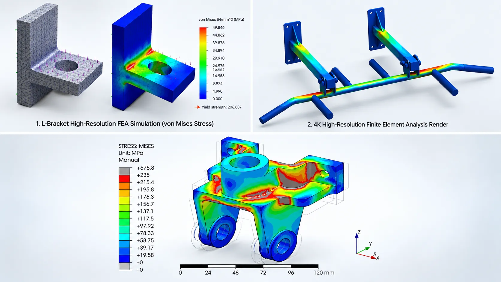
Rather than testing an actual product through multiple physical prototypes, engineers create a digital model and divide it into thousands or sometimes millions of smaller elements connected by nodes. These elements collectively form what is known as a finite element mesh.
The software then solves complex mathematical equations for every element, calculating how each region of the model behaves under the applied loading conditions.
This enables engineers to visualise:
- Stress distribution
- Strain
- Structural deformation
- Displacement
- Safety factors
- Contact behaviour
- Buckling
- Fatigue-prone regions
- Natural frequencies
- Dynamic responses
By analysing these results before manufacturing begins, engineering teams can identify design weaknesses early and make informed improvements, reducing development risks and overall costs.
Why is Finite Element Analysis Important?
Modern engineering products are expected to be lighter, stronger, and more efficient while meeting increasingly stringent safety and industry standards. Achieving these objectives through physical testing alone is often impractical due to the time and expense involved.
Finite Element Analysis provides a virtual testing environment where multiple design iterations can be evaluated quickly, enabling engineers to optimize performance before fabrication.
Some of the primary benefits of FEA include:
- Reduced Development Costs: Each physical prototype requires material, machining, assembly, and testing. FEA minimises the number of prototypes required by validating designs digitally during the early development stages.
- Faster Product Development: Simulation allows engineers to evaluate multiple design alternatives within days instead of waiting weeks for physical testing. This accelerates engineering workflows and shortens product development cycles.
- Improved Product Safety: By identifying excessive stresses, deformation, or potential failure locations before production, FEA helps engineers create safer and more reliable products.
- Better Material Optimisation: Many products are intentionally overdesigned due to uncertainty about structural performance. FEA enables engineers to remove unnecessary material while maintaining strength, reducing both weight and manufacturing costs.
- Enhanced Design Confidence: Simulation results provide quantitative engineering data that supports design decisions, regulatory compliance, and customer approval processes.
Understanding Static FEA
Static FEA, also known as Static Structural Analysis, evaluates how a component behaves when loads are applied gradually and remain essentially constant over time.
In static analysis, engineers assume that the loading changes slowly enough that inertia and acceleration effects can be ignored. The structure reaches an equilibrium condition where the applied forces are balanced by internal stresses.
In simple terms, Static FEA answers questions such as:
- Will this structure withstand the applied load?
- How much will it deform?
- Where are the highest stresses located?
- Does the design meet the required safety factor?
- Is any part likely to yield or fail?
Because the loading remains constant, the simulation focuses primarily on stress, displacement, and structural integrity rather than motion or vibration.
How Static FEA Works
A typical Static FEA workflow consists of the following steps:
- Create a 3D CAD model.
- Assign material properties such as Young’s modulus, Poisson’s ratio, and yield strength.
- Generate the finite element mesh.
- Apply fixtures or boundary conditions.
- Apply static loads such as forces, pressure, gravity, or torque.
- Solve the mathematical equations.
- Evaluate stress, deformation, strain, reaction forces, and factor of safety.
Because the calculations do not involve changing loads over time, Static FEA is generally faster and less computationally intensive than Dynamic FEA.
Common Types of Static Loads
Static loading conditions include:
- Constant mechanical forces
- Uniform pressure
- Dead loads
- Equipment weight
- Gravity
- Bolt preload
- Constant torque
- Thermal expansion under steady-state conditions
These loads remain relatively unchanged throughout the simulation.
Typical Applications of Static FEA
Static analysis is one of the most widely used forms of Finite Element Analysis across mechanical and structural engineering because many industrial components primarily experience steady loading conditions.
Common applications include:
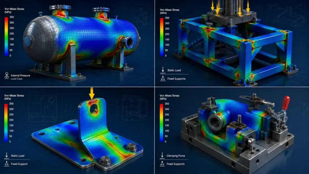
- Structural Frames: Industrial equipment frames, machine bases, support structures, lifting frames, and welded assemblies are typically analysed using Static FEA to verify structural strength and minimise excessive deflection.
- Pressure Vessels: Pressure vessels, storage tanks, and process equipment are subjected to internal pressure that is generally steady during operation. Static FEA helps engineers assess stress concentrations, shell deformation, and compliance with design standards.
- Sheet Metal Components: Brackets, cabinets, enclosures, electrical panels, and fabricated sheet metal assemblies are commonly validated using Static FEA to ensure they can safely support operational loads without excessive deformation.
- Machine Components: Shaft supports, bearing housings, gearbox casings, mounting brackets, and structural machine parts often experience constant service loads that are well suited to static structural analysis.
- Industrial Fixtures and Jigs: Manufacturing fixtures, welding jigs, assembly tools, and workholding equipment are routinely analysed using Static FEA to verify rigidity and maintain dimensional accuracy during production.
Advantages of Static FEA
- Faster Simulation Times: Because time-dependent calculations are not required, simulations typically solve much faster than dynamic analyses, allowing engineers to evaluate multiple design concepts efficiently.
- Lower Computational Requirements: Static FEA generally requires less processing power and memory, making it suitable for analysing large assemblies without excessive computational resources.
- Easier Result Interpretation: Stress contours, displacement plots, and safety factors are relatively straightforward to interpret, enabling engineers to make informed design decisions quickly.
- Cost-Effective Design Validation: For components subjected primarily to constant loads, Static FEA provides accurate and reliable results without the added complexity of dynamic simulations.
- Supports Early Design Optimisation: Engineers can identify overstressed regions, optimize geometry, reduce unnecessary material, and improve manufacturability before moving to detailed design or production.
Understanding Dynamic FEA
While Static FEA evaluates structures subjected to constant or slowly applied loads, many engineering systems operate under conditions where loads change continuously with time. Machines vibrate, vehicles accelerate and brake, rotating equipment experiences cyclic forces, and industrial components are exposed to shocks and impacts. In these situations, engineers must account for inertia, acceleration, damping, and changing load magnitudes.
This is where Dynamic FEA becomes essential.
Dynamic Finite Element Analysis (Dynamic FEA) is used to predict how a structure responds to time-varying loads. Unlike static analysis, which assumes equilibrium throughout the loading process, Dynamic FEA evaluates how a component behaves as forces change with time and motion.
In Dynamic FEA, the software solves not only for stress and deformation but also considers:
- Acceleration
- Velocity
- Inertia forces
- Damping effects
- Time-dependent displacement
- Frequency response
- Resonance behaviour
- Energy transfer
These additional factors allow engineers to understand how structures behave in real operating environments where motion and vibration significantly influence performance.
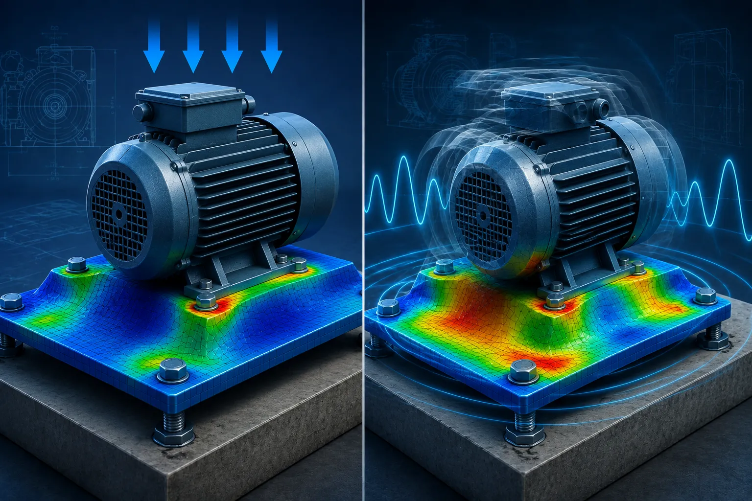
For example, consider a conveyor support frame operating inside a manufacturing plant. Although the frame may safely withstand its static weight, continuous motor vibrations could eventually cause fatigue cracks if resonance occurs. Static analysis alone cannot predict this behaviour, whereas Dynamic FEA can identify the potential issue before production.
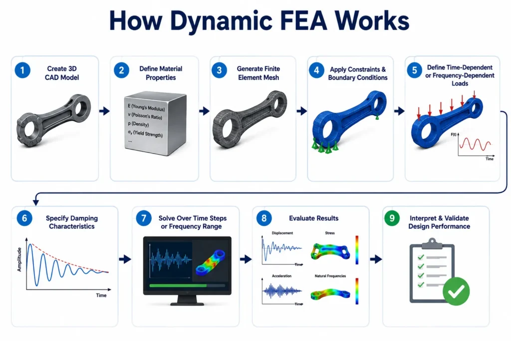
How Dynamic FEA Works
A typical Dynamic FEA process includes:
- Creating the 3D CAD model.
- Defining accurate material properties, including density.
- Generating a high-quality finite element mesh.
- Applying realistic constraints and boundary conditions.
- Defining time-dependent or frequency-dependent loads.
- Specifying damping characteristics.
- Solving the governing equations over multiple time steps or frequency ranges.
- Evaluating displacement, stress, vibration, acceleration, and natural frequencies.
Because thousands of incremental calculations may be required, Dynamic FEA generally demands greater computational power and longer solution times than static structural analysis.
Common Types of Dynamic Analysis
1. Modal Analysis
Modal Analysis determines a structure’s natural frequencies and mode shapes.
Every structure has frequencies at which it naturally prefers to vibrate. If operating equipment excites one of these frequencies, resonance may occur, dramatically increasing vibration amplitudes and potentially leading to premature failure.
Modal Analysis helps engineers answer questions such as:
- What are the natural frequencies?
- Which vibration modes are most critical?
- Will operating speeds cause resonance?
- Does the design require additional stiffness?
Typical Applications
- Electric motors
- Pumps
- Industrial fans
- Rotating machinery
- Aerospace structures
- Automotive components
- Machine tool frames
2. Harmonic Analysis
Harmonic Analysis evaluates how a structure responds to continuously repeating sinusoidal loads.
Rather than examining a single force, engineers analyse the response across a range of excitation frequencies.
This helps determine:
- Peak vibration amplitudes
- Frequency response
- Resonance locations
- Dynamic stress levels
Typical Applications
- Compressors
- Gearboxes
- Turbines
- Conveyor systems
- HVAC equipment
- Rotating industrial machinery
3. Transient Dynamic Analysis
Transient Analysis studies loads that vary over time and are not repetitive.
These loads may include:
- Sudden impacts
- Emergency stops
- Falling objects
- Shock loading
- Machine start-up
- Machine shutdown
- Explosion loads
- Earthquake events
Because these events change rapidly, engineers evaluate the complete time history of the response rather than a steady operating condition.
Typical Applications
- Material handling equipment
- Heavy machinery
- Automotive crash components
- Industrial presses
- Mining equipment
- Defence equipment
4. Random Vibration Analysis
Some engineering systems experience vibration from unpredictable external sources.
Rather than applying one specific force, engineers analyse vibration statistically.
- Aircraft vibration
- Transportation loads
- Railway equipment
- Offshore platforms
- Electronic equipment
- Satellite components
5. Response Spectrum Analysis
Response Spectrum Analysis is widely used in earthquake engineering.
Instead of simulating an entire earthquake, engineers use predefined response spectra that represent expected seismic behaviour.
Typical applications include:
- Industrial plants
- Pressure vessels
- Structural steel buildings
- Pipe support systems
- Petrochemical facilities
- Power plants
Advantages of Dynamic FEA
- Predicts Real Operating BehaviourDynamic analysis closely represents actual operating conditions by considering changing loads, inertia, and vibration. This enables engineers to design products that perform reliably throughout their service life.
- Identifies Resonance ProblemsOne of the greatest strengths of Dynamic FEA is its ability to detect resonance before manufacturing begins. Avoiding resonance helps prevent:
- Excessive vibration
- Noise
- Fatigue cracking
- Bearing failures
- Structural damage
- Improves Fatigue Life PredictionsRepeated loading often causes fatigue failure even when stresses remain below the material’s yield strength. Dynamic analysis helps engineers evaluate cyclic loading and improve product durability.
- Supports High-Speed Machinery DesignModern industrial equipment frequently operates at high rotational speeds where inertia forces become significant. Dynamic FEA assists engineers in validating designs for:
- Rotating equipment
- Robotics
- CNC machines
- Manufacturing automation
- Aerospace systems
- Reduces Unexpected FailuresBy understanding how components respond under real operating conditions, engineers can eliminate potential design weaknesses before production. This reduces maintenance costs, downtime, and warranty claims.
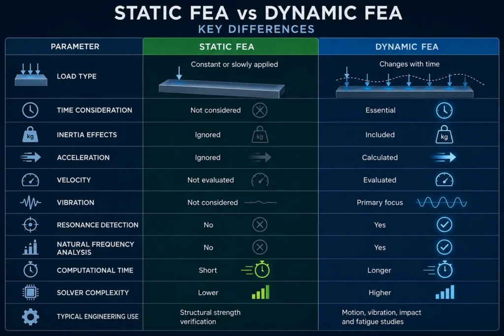
Static FEA vs Dynamic FEA: Key Differences
Although both approaches fall under Finite Element Analysis, they are intended for different engineering scenarios.
When Should You Use Static FEA?
Static Structural Analysis is generally the best choice when loads remain relatively constant throughout operation.
Typical situations include:
- Equipment Support Frames: Industrial support structures primarily experience steady gravitational and operational loads.
- Pressure Vessels: Internal operating pressure changes slowly during normal service.
- Storage Tanks: Liquid loads remain relatively stable under normal operating conditions.
- Sheet Metal Assemblies: Electrical enclosures, brackets, cabinets, and fabricated components usually support constant service loads.
- Machine Bases: Heavy machine foundations typically experience limited dynamic effects and can often be evaluated accurately using Static FEA.
- Lifting Fixtures: Many lifting tools are designed for maximum static loads rather than continuous vibration.
When Should You Use Dynamic FEA?
Dynamic analysis becomes essential whenever loading changes significantly during operation.
Choose Dynamic FEA when analysing:
- Rotating Equipment: Motors, turbines, compressors, pumps, and fans continuously generate dynamic forces.
- Industrial Robots: Robot arms accelerate, decelerate, and change direction rapidly.
- Conveyor Systems: Moving products generate varying loads and vibration throughout operation.
- Automotive Components: Suspension systems, chassis, engine mounts, and drivetrain components experience continuously changing loads.
- Aerospace Structures: Aircraft components undergo vibration, aerodynamic loading, and fatigue throughout flight.
- Heavy Manufacturing Equipment: Stamping presses, crushers, forging machines, and mining equipment frequently experience impact loading.
Can Static FEA Replace Dynamic FEA?
This is one of the most common misconceptions in engineering simulation.
The answer is no.
Although Static FEA is faster and easier to perform, it cannot accurately predict behaviour influenced by:
- Inertia
- Acceleration
- Vibration
- Resonance
- Shock loading
- Cyclic loading
- Frequency-dependent responses
Similarly, using Dynamic FEA for every project is neither practical nor economical. Dynamic simulations require additional modelling effort, detailed loading information, and greater computational resources.
The most effective engineering approach is to select the simulation method that accurately represents the product’s real operating conditions.
Common Mistakes When Selecting an FEA Method
- Ignoring Dynamic Loads: Assuming that a vibrating machine behaves like a static structure can underestimate stresses and fatigue damage.
- Overcomplicating Simple Problems: Running Dynamic FEA for components subjected only to constant loading increases project time without improving design accuracy.
- Incorrect Boundary Conditions: Even the most advanced analysis will produce unreliable results if supports, fixtures, or load paths are defined incorrectly.
- Poor Mesh Quality: An excessively coarse mesh may overlook stress concentrations, while an unnecessarily fine mesh increases solution time without significant accuracy gains.
- Neglecting Material Properties: Dynamic analyses require accurate density and damping properties in addition to elastic material data. Using incomplete material definitions can significantly affect simulation results.
How Engineers Decide Between Static and Dynamic FEA
Selecting the appropriate Finite Element Analysis (FEA) method is not simply a matter of preference. It is a critical engineering decision based on how a product behaves during its actual operating life. Every component experiences different loading conditions, environmental factors, and performance requirements. The goal is to choose a simulation method that accurately reflects these real-world conditions while balancing analysis time and computational effort.
Experienced design engineers typically evaluate several factors before deciding whether Static FEA or Dynamic FEA is the most suitable approach.
1. Nature of the Applied Load
The first question engineers ask is: Does the load remain constant, or does it change with time?
If a structure supports a steady weight, internal pressure, or constant force, Static FEA is usually sufficient. Examples include equipment frames, storage racks, pressure vessels, structural brackets, and machine bases.
However, if the load varies because of acceleration, vibration, impact, rotating machinery, or repeated cycles, Dynamic FEA becomes necessary to accurately predict structural behaviour.
2. Operating Speed
The operating speed of a machine significantly influences the type of analysis required.
For slow-moving or stationary equipment, inertia effects are often negligible, making Static FEA an appropriate choice.
Conversely, high-speed rotating machinery such as turbines, pumps, compressors, centrifuges, and electric motors generate dynamic forces that cannot be ignored. In these cases, Dynamic FEA helps engineers evaluate vibration characteristics, resonance risks, and fatigue life.
3. Importance of Vibration
Not every engineering project requires vibration analysis, but for many industrial systems, vibration directly affects performance and reliability.
Engineers generally ask:
- Will vibration reduce product life?
- Can resonance occur within the operating speed range?
- Will excessive vibration affect accuracy or safety?
If vibration is a design concern, analyses such as Modal Analysis, Harmonic Analysis, or Transient Dynamic Analysis are often performed before finalising the design.
4. Product Safety Requirements
Products operating in safety-critical environments demand a higher level of engineering validation.
Examples include:
- Pressure vessels
- Lifting equipment
- Structural steel systems
- Aerospace assemblies
- Automotive safety components
- Medical equipment
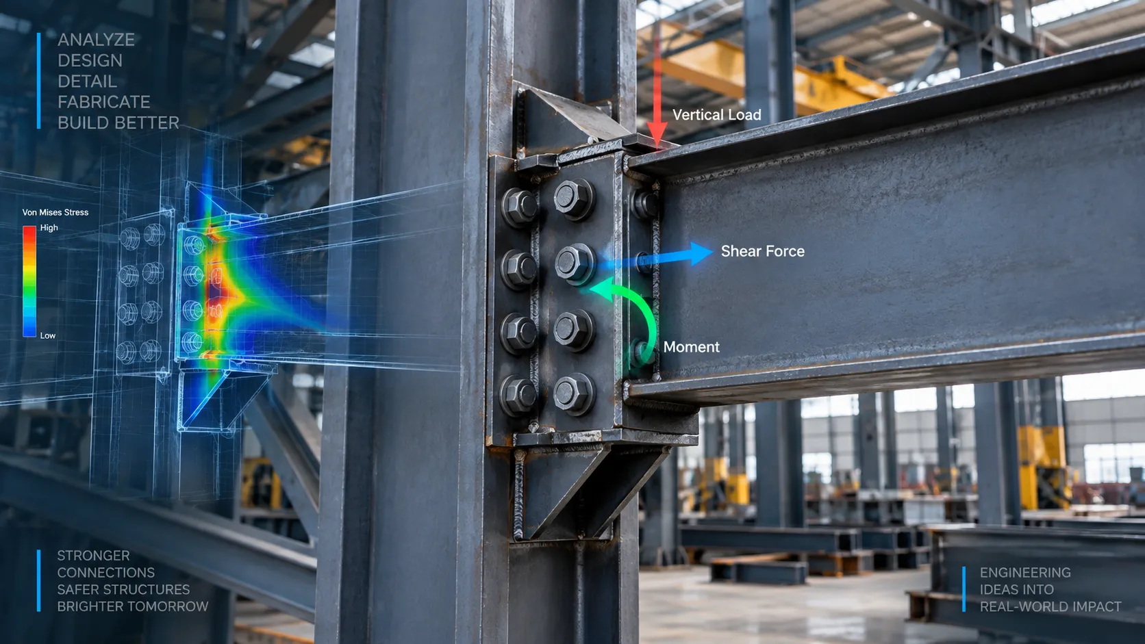
Although Static FEA may satisfy initial design verification, engineers frequently supplement it with Dynamic FEA to evaluate extreme operating conditions, accidental impacts, vibration, or seismic loading.
5. Industry Standards and Regulations
Many industries require simulation methods that comply with recognised engineering standards.
For example:
- Pressure vessels may require stress evaluation according to ASME design principles.
- Structural systems in seismic regions often require Response Spectrum Analysis.
- Automotive and aerospace industries commonly include fatigue and vibration assessments during product validation.
Choosing the correct Finite Element Analysis method helps engineers demonstrate compliance with customer specifications and regulatory requirements while improving confidence in product performance.
Industry Applications of Static and Dynamic FEA
1. Oil & Gas Industry
Oil and gas facilities contain numerous components that require structural verification before fabrication and installation.
Typical Static FEA Applications
- Pressure vessels
- Heat exchangers
- Storage tanks
- Pipe supports
- Structural platforms
- Equipment foundations
Typical Dynamic FEA Applications
- Compressor skids
- Rotating pumps
- Turbine foundations
- Offshore structures
- Vibration-sensitive piping systems
Dynamic analysis is particularly valuable for rotating equipment where continuous vibration can lead to fatigue failure if resonance is not identified during the design stage.
2. Industrial Machinery
Manufacturing equipment often combines both static and dynamic loading conditions.
For example, a machine frame may be analysed using Static FEA to verify structural strength, while the moving mechanisms undergo Dynamic FEA to evaluate vibration and acceleration.
Typical applications include:
- CNC machine structures
- Conveyor systems
- Robotic equipment
- Packaging machinery
- Material handling equipment
- Industrial automation systems
3. Automotive Industry
Modern vehicles are designed to achieve maximum performance while reducing weight.
Finite Element Analysis enables automotive engineers to optimise designs without compromising safety.
Applications include:
- Suspension systems
- Engine mounts
- Chassis structures
- Brake components
- Steering assemblies
- Battery enclosures
- Electric vehicle components
Dynamic simulations help predict vibration, impact behaviour, and fatigue performance under real driving conditions.
4. Aerospace Industry
Aircraft components operate under continuously changing aerodynamic forces and stringent safety requirements.
Common FEA applications include:
- Aircraft fuselage structures
- Wing assemblies
- Landing gear
- Engine components
- Interior support structures
- Satellite equipment
Dynamic analyses evaluate vibration, flutter, fatigue, and transient loading to ensure long-term structural integrity.
5. Heavy Equipment and Construction Machinery
Construction and mining equipment frequently experience extreme operating conditions, including repeated impacts and cyclic loading.
Typical applications include:
- Excavator booms
- Crane structures
- Loader arms
- Hydraulic cylinders
- Dump truck frames
- Drilling equipment
Dynamic FEA enables engineers to predict fatigue damage and improve durability before manufacturing.
6. Consumer Product Development
Finite Element Analysis is equally valuable for consumer products, where reducing weight, material usage, and manufacturing costs is a priority.
Applications include:
- Home appliances
- Fitness equipment
- Furniture
- Electronic product enclosures
- Power tools
- Plastic moulded products
Static analysis validates structural strength, while Dynamic FEA helps improve vibration behaviour, durability, and user comfort.
How FEA Improves Product Development
1. Reduces Physical Prototyping
Traditional product development often involved manufacturing several prototypes before arriving at the final design. Each prototype required additional material, machining, labour, and testing costs.
With FEA, engineers can evaluate multiple design concepts digitally, identifying weaknesses early and significantly reducing the number of physical prototypes required.
2. Accelerates Design Optimisation
Repetitive design validation can be streamlined using SolidWorks API & CAD Automation, allowing engineers to automate simulation-related workflows and reduce engineering effort.
They can optimise:
- Wall thickness
- Rib placement
- Structural reinforcement
- Material selection
- Weld locations
- Mounting configurations
This iterative process results in lighter, stronger, and more cost-effective products.
3. Improves Product Reliability
Identifying stress concentrations before production helps prevent premature failures in the field.
FEA enables engineers to improve:
- Structural integrity
- Service life
- Fatigue resistance
- Load distribution
- Overall product durability
4. Supports Better Manufacturing Decisions
Production tooling such as Jigs & Fixtures Design can also benefit from structural analysis to ensure rigidity and dimensional accuracy during manufacturing.
Engineers can determine whether a design:
- Requires additional reinforcement
- Can be manufactured economically
- Meets safety requirements
- Contains unnecessary material
- Is suitable for production
This collaboration between design and manufacturing reduces engineering rework and shortens development timelines.
Why Choose Immersiv Techsphere for FEA Services?
At Immersiv Techsphere, we help manufacturers, OEMs, engineering consultants, and product development companies make informed design decisions through accurate Finite Element Analysis and engineering simulation.
Our engineering team combines practical design experience with advanced simulation techniques to validate product performance before manufacturing begins.
Our FEA capabilities include:
- Static Structural Analysis
- Dynamic Structural Analysis
- Modal Analysis
- Vibration Analysis
- Linear Stress Analysis
- Contact Analysis
- Buckling Analysis
- Thermal-Structural Analysis
- Design Optimisation
- Engineering Validation
We work with a wide range of industries, including:
- Industrial Equipment
- Oil & Gas
- Process Equipment
- Material Handling
- Heavy Machinery
- Automotive
- Consumer Products
- Furniture
- Sheet Metal Fabrication
Our objective is not just to generate simulation reports but to provide engineering insights that help improve safety, reduce development costs, and enhance product performance.
Whether you need to validate a new design, optimise an existing product, or investigate structural failures, our FEA specialists can support your engineering team with reliable, data-driven analysis.
Frequently Asked Questions (FAQs)
Static FEA evaluates structures under constant or slowly changing loads, while Dynamic FEA analyses structures subjected to time-dependent loads such as vibration, impact, acceleration, or cyclic forces.
Static FEA is suitable for products experiencing steady loading conditions, including machine frames, pressure vessels, structural supports, brackets, sheet metal components, and equipment foundations.
Dynamic FEA should be used when products experience changing loads, vibration, impact, rotating motion, cyclic loading, or resonance effects that cannot be accurately captured through static analysis.
Not necessarily. The accuracy depends on whether the chosen simulation method matches the real operating conditions. Using the appropriate analysis is more important than selecting the more complex one.
Finite Element Analysis is widely used in automotive, aerospace, oil and gas, heavy machinery, industrial equipment, consumer products, marine engineering, and construction industries.
No. Static FEA does not account for vibration, inertia, acceleration, or resonance. These require Dynamic FEA methods such as Modal, Harmonic, or Transient Analysis.
Popular FEA software includes ANSYS, SolidWorks Simulation, Abaqus, Autodesk Inventor Nastran, Siemens Simcenter, MSC Nastran, and Altair HyperWorks. The choice depends on the complexity of the simulation and project requirements.
FEA enables engineers to validate and optimise designs virtually, reducing the need for multiple physical prototypes, minimising engineering rework, shortening development cycles, and improving product reliability before manufacturing.
Yes. Many engineering projects use both methods. Static FEA verifies structural strength under steady loads, while Dynamic FEA evaluates vibration, fatigue, impact, and time-dependent behaviour for a complete design assessment.
Immersiv Techsphere provides comprehensive Finite Element Analysis services, including static and dynamic structural simulations, vibration analysis, design optimisation, and engineering validation to help manufacturers develop safer, more efficient, and production-ready products.
Conclusion
Choosing between Static FEA and Dynamic FEA is one of the most important decisions in engineering simulation. Although both methods are based on the principles of Finite Element Analysis, they address fundamentally different design challenges.
Static FEA is ideal for components subjected to steady or slowly applied loads, making it the preferred choice for evaluating structural strength, deformation, and safety under constant operating conditions.
Dynamic FEA, on the other hand, is essential when loads vary with time or when vibration, acceleration, inertia, impact, or fatigue influence product performance. It enables engineers to predict real-world behaviour, avoid resonance, and improve long-term reliability.
Rather than viewing one method as superior to the other, engineers should select the approach that best represents the product’s actual operating environment. In many projects, both static and dynamic analyses complement each other, providing a more comprehensive understanding of structural performance.
As products become increasingly lightweight, efficient, and complex, Finite Element Analysis will continue to play a vital role in helping manufacturers reduce development costs, accelerate innovation, and deliver reliable products with greater confidence.
Have a Project in Mind?
Need help with 3D animation, industrial visualization, HSE training animation, or product visualization? Tell us about your project and our team will get back to you.