

Table of Contents
Introduction
In structural analysis, getting the geometry right is only half the job. The way you constrain and load a model can make a significant difference to the simulation results.
This is where FEA boundary conditions in Solidworks Simulation become important.
A model may look perfectly designed, but incorrect fixtures, unrealistic loads or missing contact definitions can produce misleading stress and displacement results.
So, how do you define boundary conditions correctly? And what mistakes should you avoid?
Let’s break it down.
What Are Boundary Conditions in FEA?
Boundary conditions define how a component or assembly behaves under specific loading conditions.
In simple terms, they tell the simulation:
- Where is the component supported?
- Which directions can it move?
- Where and how are forces applied?
- How do connected components interact?
In Solidworks Simulation, boundary conditions mainly involve fixtures, loads and contact interactions.
These inputs help the solver understand how the model behaves under the selected operating conditions.
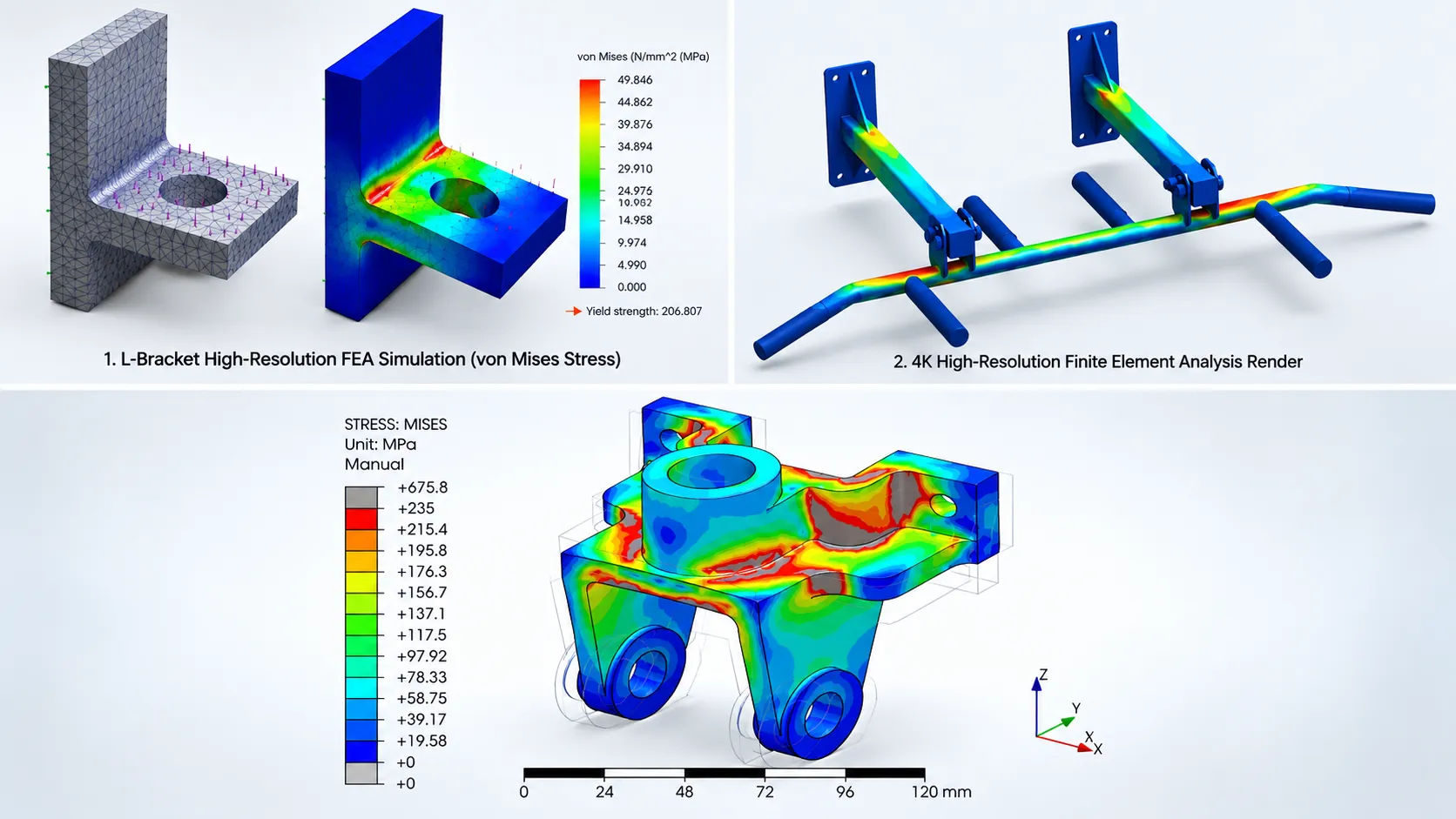
FEA is widely used to evaluate the structural performance of mechanical components before manufacturing. Through FEA simulation and structural analysis services, engineers can assess stress distribution, deformation, fatigue behaviour and potential design weaknesses under different operating conditions.
Types of Boundary Conditions in Solidworks Simulation
1. Fixtures (Supports)
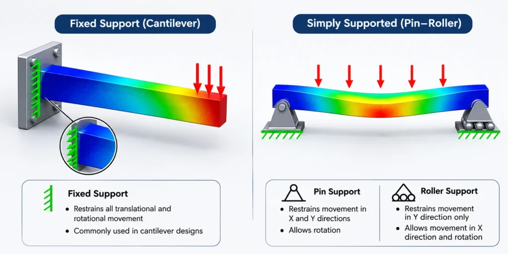
Fixtures define how the model is restrained.
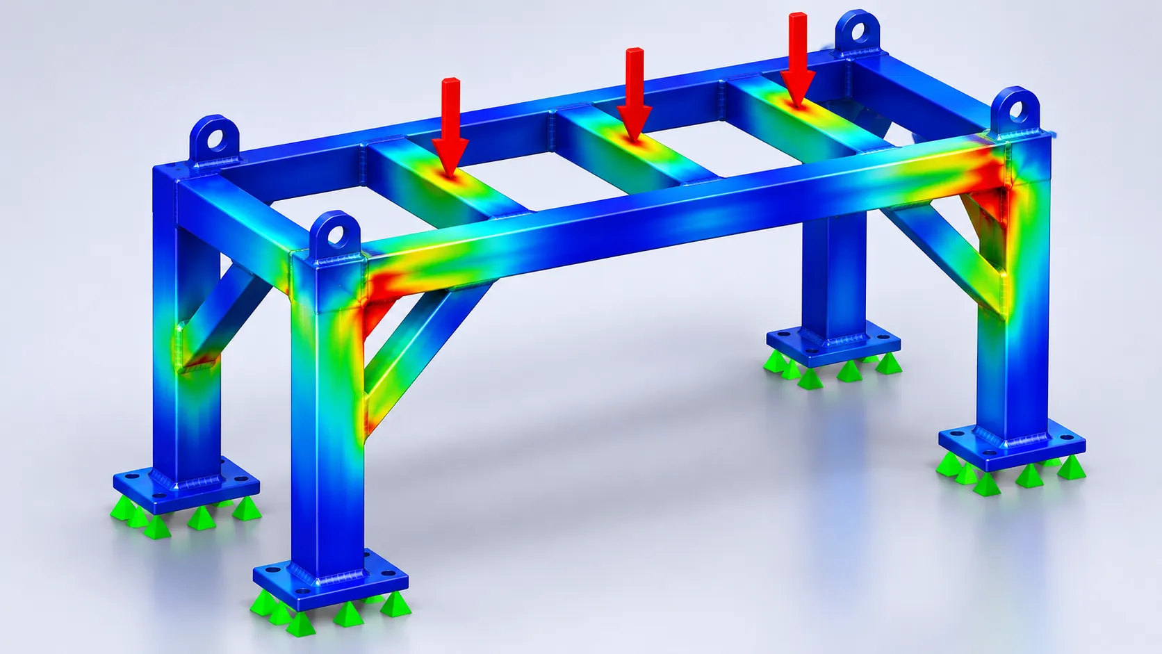
For example, consider a cantilever beam fixed at one end. The supported face cannot move or rotate under an ideal fixed restraint.
In Solidworks Simulation, common fixture options include:
- Fixed Geometry
- Roller/Slider
- Use Reference Geometry
- Advanced Fixtures for specific restraint conditions
The important point is to select restraints that represent the actual mounting or support arrangement.
2. Applied Loads
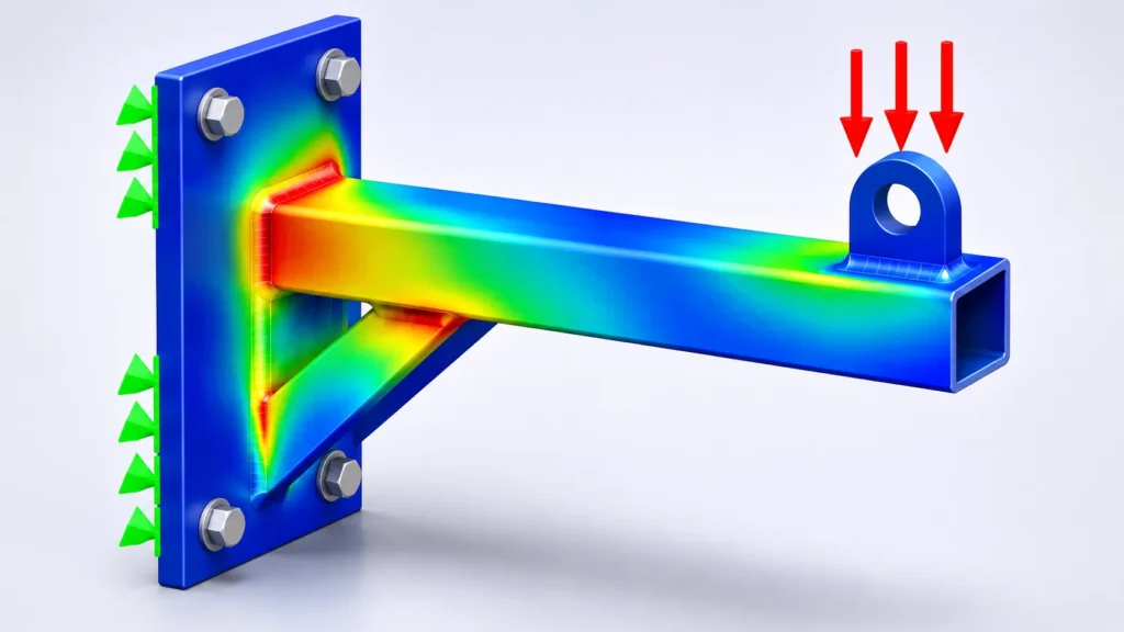
Loads represent external forces acting on the model.
Common examples include:
- Force
- Pressure
- Torque
- Gravity
- Centrifugal force
For example, a pressure vessel experiences pressure acting on its internal surfaces, while a machine frame may experience forces transferred through mounted equipment.
The load direction, magnitude and application area must reflect the real operating conditions.
3. Contact Conditions
When working with assemblies, components may touch, separate or transfer forces between one another.
Solidworks Simulation provides contact definitions such as:
- Bonded contact
- No Penetration contact
- Allow Penetration contact, where supported by the selected study and contact formulation
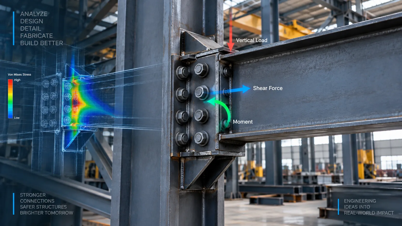
Choosing the correct contact condition is essential. Treating two bolted or sliding components as permanently bonded, for example, may not represent their actual mechanical behaviour.
Understanding how components transfer loads through their connections is equally important in structural design. Explore structural connection design and how analysis helps prevent fabrication problems for more insights into evaluating structural connections.
Common Boundary Condition Setup Errors and How to Avoid Them
Even a well-built simulation study can produce unreliable results if the boundary conditions are not realistic. Here are some mistakes worth checking before running an analysis.
1. Applying Fixed Fixtures Everywhere
This is one of the most common mistakes.
Fixing too many faces can make a component artificially stiff. It restricts movement that might actually occur in the real assembly, affecting stress and displacement results.
How to avoid it: Apply fixtures only where the component is genuinely supported, bolted, mounted or restrained. Consider the actual mounting arrangement instead of fixing faces simply to make the model stable.
2. Using Incorrect Load Directions
Applying a force in the wrong direction or using an incorrect magnitude can completely change the simulation outcome.
For example, a vertical load on a machine support should not be applied horizontally unless that represents an actual operating condition.
How to avoid it: Check the load direction, coordinate system, units and magnitude. Use the correct reference geometry when defining directional loads.
3. Ignoring Contact Between Components
In an assembly, components may be bolted, welded, pressed together or allowed to slide.
Using bonded contact for every connection can make the assembly behave more rigidly than it should.
How to avoid it: Define contact conditions according to the actual connection. Use bonded contact for appropriate rigid connections and No Penetration contact where components must not pass through each other. Consider friction when it is relevant to the physical behaviour and supported by the study.
4. Under-Constraining or Over-Constraining the Model
A model with insufficient restraints may move as a rigid body, causing solver errors or instability.
On the other hand, excessive restraints can prevent natural deformation and produce unrealistic results.
How to avoid it: Review all degrees of freedom (translations and rotations) that should be restrained. Make sure the model is stable without restricting movement that should remain possible.
5. Applying Loads to Unrealistic Locations
Applying a concentrated force to a small edge or vertex may create artificially high local stresses.
This can lead to stress concentrations or mathematical singularities, where the calculated peak stress increases with mesh refinement rather than converging to a finite value.
Correct boundary conditions alone do not guarantee reliable simulation results. Mesh quality also plays an important role in capturing stress concentrations around holes, fillets, contact regions and load application points. Learn more about FEA mesh quality and mesh selection and how mesh refinement affects simulation accuracy.
How to avoid it: Represent the actual load-transfer mechanism. Where appropriate, distribute forces over realistic contact areas or use suitable bearing, pressure or connection representations.
A Practical Checklist Before Running FEA in Solidworks
Before solving a static study, take a few minutes to review the setup.
- Fixtures represent actual supports and mounting conditions.
- All applied loads have correct magnitudes and directions.
- Units and coordinate systems are checked.
- Assembly contact conditions reflect real connections.
- The model has sufficient restraints without unnecessary restrictions.
- No unintended gaps, interferences or disconnected components affect load transfer.
- Reaction forces are consistent with the applied loading.
- The deformed shape is physically reasonable.
Why Correct Boundary Conditions Matter
The accuracy of an FEA study depends on more than the solver or mesh quality. It starts with how closely the simulation represents the real physical system.
Properly defined boundary conditions help engineers evaluate how mechanical components respond to real-world loading conditions. This makes FEA an important part of design validation, helping identify potential weaknesses before manufacturing. Read more about how FEA simulation helps identify design failures before manufacturing.
At Immersiv Techsphere, we use Solidworks Simulation for FEA and structural design validation to help manufacturers evaluate stress, deformation and structural performance before manufacturing.
From industrial equipment and machine frames to sheet-metal components and fitness equipment, realistic simulation setup helps identify potential design issues early.
The objective is simple: make better engineering decisions before production begins.
Frequently Asked Questions (FAQs)
Product rendering helps technical buyers visualise a product’s construction, materials, surface finishes and design features through realistic 3D images. It makes product details easier to understand before manufacturing or purchasing decisions.
Yes. 3D product rendering can represent materials such as stainless steel, aluminium, powder-coated metal, wood, glass and plastic, including different colours, textures and surface finishes.
Industrial product rendering focuses on machinery, equipment, assemblies and engineering details. Commercial product rendering focuses more on product appearance, material combinations, customisation options and presentation in real-world environments.
Yes. Product rendering can highlight specific components, assembly arrangements, surface details and functional features through close-up views, multiple camera angles and exploded views.
Yes. Product rendering can be developed using 3D CAD models before physical manufacturing begins. It allows manufacturers to showcase proposed designs, material options and product variations without producing physical prototypes.
Conclusion
Accurate FEA results start with realistic boundary conditions. Whether you are analysing a welded machine frame, a mounting bracket or an industrial equipment component, the way supports, loads and contact conditions are defined directly influences the simulation results.
In Solidworks Simulation, taking time to review fixtures, load directions and component interactions can help avoid common setup errors and produce more meaningful engineering insights.
At Immersiv Techsphere, we use Solidworks Simulation for FEA and structural design validation to help manufacturers evaluate component behaviour, identify potential design weaknesses and make informed engineering decisions before manufacturing.
Because a reliable simulation is not just about running the analysis; it is about representing the actual engineering conditions correctly.
Have a Project in Mind?
Need help with 3D animation, industrial visualization, HSE training animation, or product visualization? Tell us about your project and our team will get back to you.