

Table of Contents
Introduction
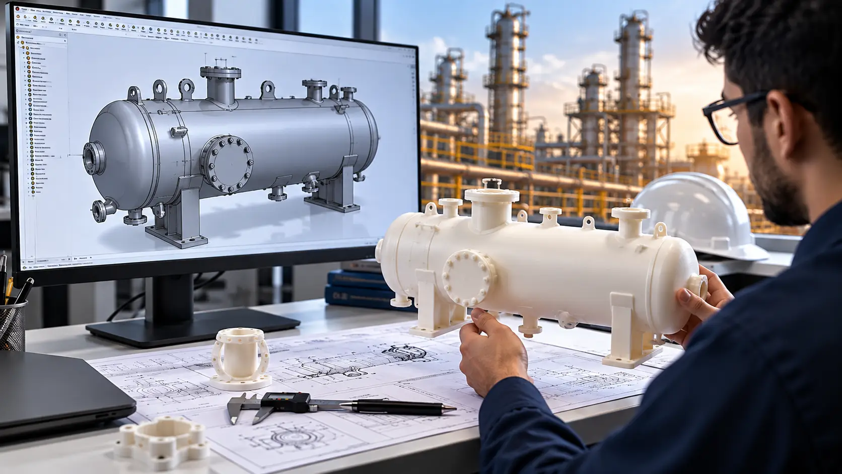
Reverse Engineering provides a practical way to turn an existing physical product, component, or assembly into an accurate and editable CAD model when the original design data is unavailable, incomplete, outdated, or difficult to modify.
Manufacturers regularly face this situation. A machine may have been designed years ago, but its original CAD files are no longer available. A replacement component may exist only as a physical part. A supplier may provide a sample without complete engineering documentation. An older product may need to be redesigned for a new manufacturing process.
Starting the design from scratch is possible, but it may require significant time and may introduce unnecessary differences from the existing product.
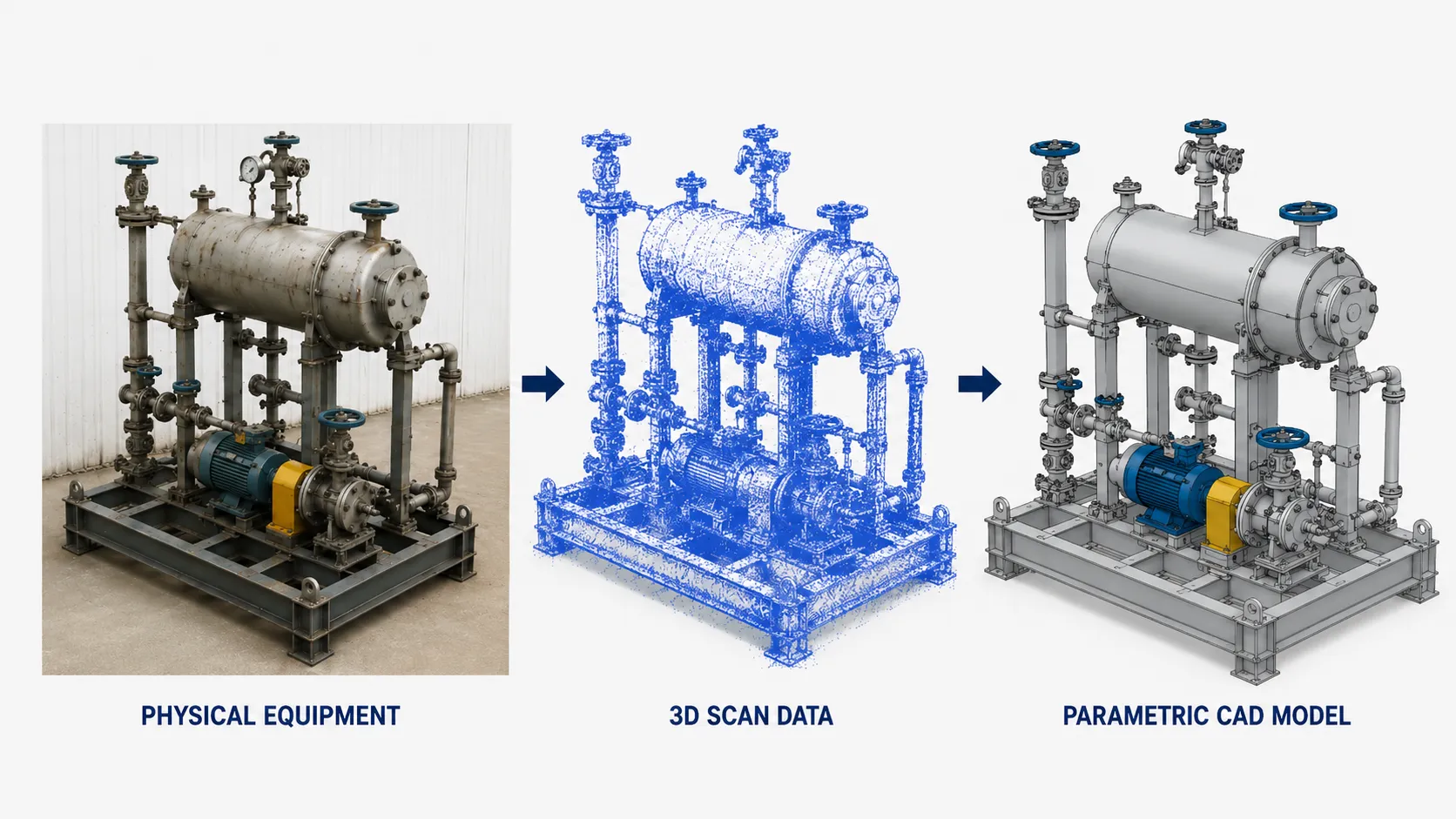
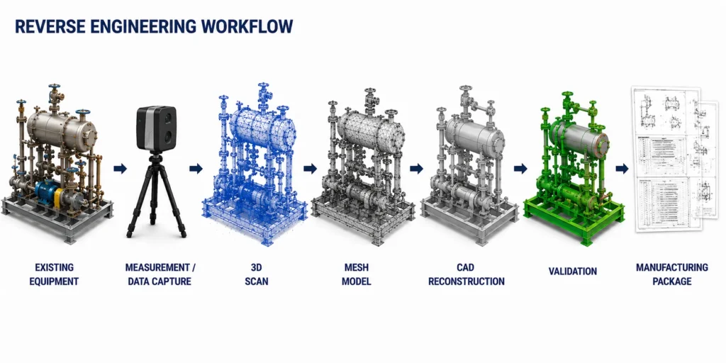
Reverse Engineering offers another approach: capture the physical product, understand its geometry and design intent, reconstruct the CAD model, validate it against the original component, and prepare the resulting design for manufacturing.
The process can involve physical measurements, 3D scanning, point clouds, mesh processing, CAD reconstruction, parametric modeling, dimensional inspection, and manufacturing documentation.
The objective is not simply to create a digital copy of a physical object. The objective is to create a usable engineering model that can be modified, analyzed, documented, and manufactured.
What Is Reverse Engineering?
Reverse Engineering in mechanical design is the process of examining an existing physical product or component and rebuilding its engineering information in a digital format.
For manufacturing applications, the process may begin with:
- An existing physical component
- A complete product or assembly
- A discontinued part
- A legacy machine
- A damaged component
- A supplier sample
- A 3D scan
- A point cloud
- An STL or OBJ mesh
- Incomplete 2D drawings
- Existing photographs and measurements
The engineer studies the available information and reconstructs the product as a CAD model.
Autodesk describes hardware reverse engineering as a process that can combine 3D scanning, measurement, mesh processing, CAD modeling, and validation to recreate or improve existing products.
For manufacturing applications, the resulting model may need to contain much more than surface geometry. It may require:
- Accurate dimensions
- Parametric features
- Material information
- Hole and mounting locations
- Thicknesses
- Fillets and chamfers
- Interfaces
- Assembly relationships
- Manufacturing tolerances
- Design intent
- Production drawings
This is what differentiates Reverse Engineering CAD from simply converting a scanned mesh into a solid body.
Why Companies Need Reverse Engineering
There are several situations where manufacturers need to recreate existing products digitally.
1. Legacy Components Without CAD Data
Older machines often remain in service for many years after their original design files have been lost or become inaccessible.
A physical component may still be available, but the engineering data required to manufacture it may not be.
Reverse engineering allows the existing component to become the reference for creating new CAD data.
2. Discontinued or Obsolete Parts
When an OEM stops manufacturing a component, companies may need to produce replacement parts internally or through another supplier.
A reverse-engineered CAD model can provide the digital foundation for manufacturing the replacement.
3. Product Redesign
Existing products can also be reverse engineered when manufacturers want to improve them.
For example, an existing component may need:
- Reduced weight
- Improved strength
- Different material
- Modified dimensions
- Better manufacturability
- New mounting interfaces
- Improved assembly
- Lower manufacturing cost
The existing product becomes the starting point rather than designing an entirely new product.
4. Supplier Changes
A manufacturer may have a physical component supplied by an existing vendor but need to transition production to another supplier.
Reconstructing the component as a CAD model can provide standardized engineering information for the new manufacturing process.
5. Missing or Incomplete Drawings
Sometimes a company has drawings, but they do not contain enough information to recreate the complete component.
In these situations, drawings can be combined with physical measurements or scan data to reconstruct the missing geometry.
How Reverse Engineering Converts a Physical Product into CAD
A successful Reverse Engineering workflow combines measurement with engineering interpretation.
Physical Product Inspection
The process begins with understanding the existing product.
Engineers inspect the component to identify:
- Overall dimensions
- Functional surfaces
- Mounting points
- Interfaces
- Fasteners
- Moving components
- Material thickness
- Symmetry
- Repeated features
- Manufacturing characteristics
- Areas affected by wear
For an assembly, individual components may need to be separated and documented before reconstruction.
This stage is important because the engineer needs to understand how the product works, not just what it looks like.
3D Scanning and Dimensional Measurement
Complex geometry can be captured using 3D scanning technologies.
Depending on the application, the data may come from:
- Laser scanners
- Structured-light scanners
- Coordinate measuring machines
- Digital calipers
- Height gauges
- Portable measurement equipment
- Photogrammetry
- Existing technical drawings
3D scanning generates a large collection of spatial measurements, commonly represented as a point cloud. The point cloud can then be processed into a mesh that provides a reference for CAD reconstruction.
NIST has documented a manufacturing example in which an impeller was scanned and the scan data was used to reverse engineer a SOLIDWORKS model before prototypes were created and validated.
From Point Cloud and Mesh to Editable CAD
One of the most important stages is converting captured physical data into useful CAD geometry.
A scan typically represents the physical surface rather than the engineering features used to create the original component.
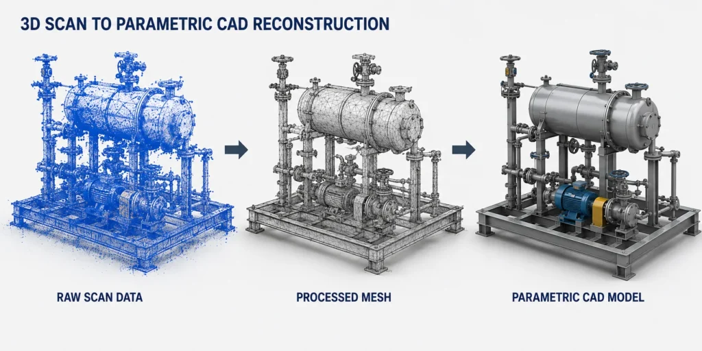
For example, a scanned cylindrical hole may contain small deviations caused by measurement noise, wear, or manufacturing variation. A CAD engineer needs to determine whether the intended design should contain a standard circular hole, counterbore, threaded feature, or another feature.
The same principle applies to:
- Planar surfaces
- Cylindrical surfaces
- Conical features
- Fillets
- Chamfers
- Slots
- Patterns
- Sheet metal bends
- Freeform surfaces
Autodesk’s current Inventor guidance explicitly notes that scan-to-CAD workflows can require cleaning the scan data followed by manual or semi-manual remodeling to create an accurate, editable parametric model.
This is why Reverse Engineering CAD should be treated as an engineering reconstruction process rather than an automatic file-conversion task.
Reconstructing Design Intent
A physical product contains both intentional design features and manufacturing imperfections.
A good reverse engineering workflow attempts to distinguish between the two.
Consider a fabricated bracket with several mounting holes. The physical component may have slight dimensional differences between holes because of manufacturing tolerances.
The CAD model should not necessarily reproduce every measured deviation.
Instead, the engineer may identify:
- Intended hole diameter
- Hole spacing
- Reference datums
- Symmetrical relationships
- Standard thickness
- Bend radius
- Mounting interface
- Required tolerance
The resulting model becomes a structured representation of the design rather than a digital record of every physical imperfection.
This is particularly important when the CAD model will later be modified or reused for another product variant.
Validation: Comparing CAD Against the Existing Product
A reverse-engineered model should be validated before it is released for manufacturing.
Validation can include:
- Dimensional comparison
- Section analysis
- Surface deviation analysis
- Hole-location verification
- Interface checking
- Overall envelope comparison
- Assembly fit verification
- Critical dimension inspection
The CAD model can be compared with the original scan or physical measurements to identify areas of deviation.
The purpose is not always to achieve zero deviation.
Some deviations may represent:
- Manufacturing tolerance
- Surface wear
- Deformation
- Measurement uncertainty
- Existing damage
- Intentional design assumptions
The engineering team must determine which differences matter for the intended application.
This distinction is especially important for replacement parts where fit and functional interfaces may be more important than reproducing cosmetic imperfections.
Making the Reverse-Engineered Model Manufacturing-Ready
Creating accurate geometry is only part of the job.
A manufacturing-ready CAD model should also consider how the component will actually be produced.
This is where Design for Manufacturing (DFM) becomes relevant.
The engineer may review:
- Material selection
- Sheet thickness
- Bend radii
- Machining access
- Welding requirements
- Standard hardware
- Hole sizes
- Tolerances
- Surface finish
- Assembly sequence
- Manufacturing process
- Inspection requirements
For example, an existing sheet metal component may have been manufactured using an older process. During reconstruction, the model can be adapted for modern laser cutting, bending, and fabrication requirements.
Similarly, a machined component may be redesigned to improve tool access or simplify machining while maintaining the required interfaces.
This approach turns Reverse Engineering into an opportunity for engineering improvement rather than simple replication.
Immersiv Techsphere’s Design for Manufacturing services focus on creating designs that balance functionality, manufacturability, and production requirements.
Reverse Engineering for Different Manufacturing Applications
Reverse engineering can support a wide range of engineering applications.
- Industrial Equipment: Existing machine components can be recreated to support equipment maintenance, redesign, and replacement-part manufacturing.
- Sheet Metal Products: Enclosures, cabinets, brackets, panels, frames, and fabricated components can be reconstructed and developed into production-ready sheet metal models.
- Machinery Components: Mechanical components such as shafts, brackets, housings, guards, fixtures, and machine elements can be recreated when original CAD files are unavailable.
- Laboratory Furniture: Existing cabinets, workbenches, frames, and accessories can be reconstructed and modified for new dimensions, layouts, or manufacturing requirements.
- Fitness Equipment: Existing frames, brackets, mechanisms, and structural components can be digitized and redesigned to support product improvement and manufacturing.
- Legacy Products: Older products can be brought into modern CAD environments for modification, documentation, and continued production.
What Makes a Reverse-Engineered CAD Model Production-Ready?
A model should not be considered manufacturing-ready simply because it visually resembles the physical component.
A production-ready model should ideally provide:
Accurate geometry
The geometry must represent the required physical interfaces and functional features.
Editable CAD structure
Parametric features should be used wherever practical so engineers can modify the model later.
Design intent
Important relationships, symmetry, dimensions, and functional features should be represented logically.
Manufacturing consideration
The design should reflect the selected manufacturing process.
Validated dimensions
Critical dimensions should be checked against reliable physical or scan data.
Engineering documentation
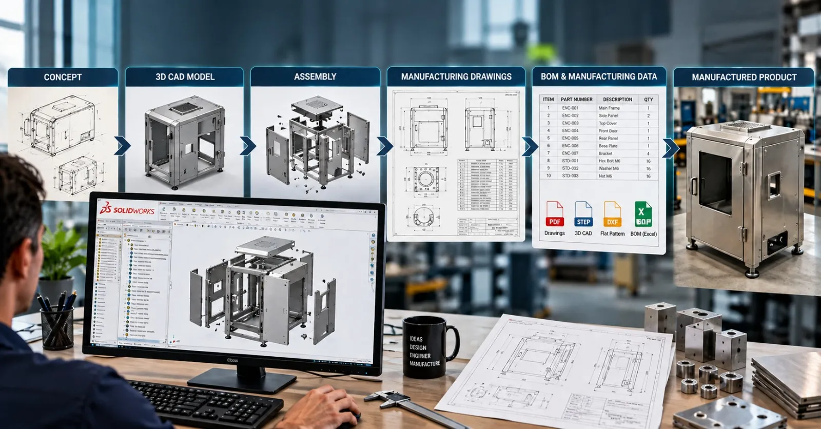
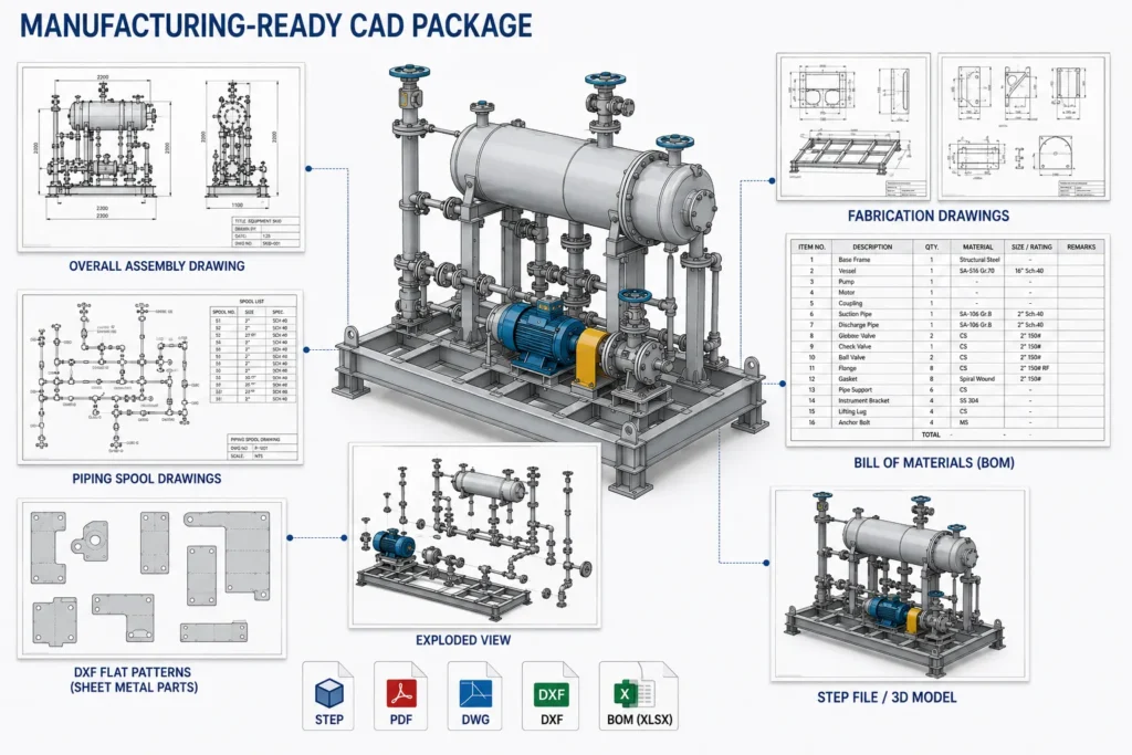
Drawings, BOMs, DXF files, STEP files, and other required outputs should be generated according to the manufacturing workflow.
This is the difference between having a 3D representation and having a usable engineering asset.
Reverse Engineering vs. 3D Scanning
3D scanning and Reverse Engineering are often discussed together, but they serve different purposes.
| 3D Scanning | Reverse Engineering |
|---|---|
| Captures physical geometry | Interprets physical geometry |
| Produces point clouds or meshes | Produces engineering CAD data |
| Focuses on measurement | Combines measurement with engineering judgment |
| Records existing surface conditions | Reconstructs design intent |
| Creates reference data | Creates editable models |
| Can support inspection | Can support redesign and manufacturing |
A scan can therefore be an important input to reverse engineering, but it is not the complete engineering process.
How Immersiv Techsphere Supports Reverse Engineering
Immersiv Techsphere supports mechanical engineering workflows that connect existing physical products with digital CAD and manufacturing documentation.
Our capabilities can include:
- Existing product and component modeling
- 3D CAD reconstruction
- Reverse engineering CAD
- Scan-to-CAD workflows
- Parametric CAD modeling
- Mechanical component reconstruction
- Sheet metal reconstruction
- Assembly modeling
- Manufacturing drawing creation
- BOM preparation
- STEP and STL preparation
- DXF generation
- Design modification
- Design for Manufacturing review
Our 3D Design & Modeling services support mechanical CAD development for industrial and manufacturing applications.
For manufacturers that need to automate repetitive engineering outputs after the model is reconstructed, our CAD Automation and Macro Development services can support workflows involving SolidWorks API, macros, automated drawings, BOM generation, and batch PDF, DXF, or STEP export.
The combination of Reverse Engineering, Mechanical Design, DFM, and CAD Automation can help manufacturers move from an existing physical product to a more structured and scalable digital engineering workflow.
Frequently Asked Questions About Reverse Engineering
Yes. A physical product can be measured or scanned and reconstructed as a CAD model. The required approach depends on the geometry, accuracy requirements, available measurement data, and intended use of the model.
Not always. Scan data typically represents physical surfaces as point clouds or meshes. Creating an editable, parametric CAD model may require engineering reconstruction and manual or semi-manual remodeling.
Yes. Recreating discontinued or obsolete components is one of the practical applications of reverse engineering. The physical component can provide the dimensional reference needed to develop a new CAD model and manufacturing documentation.
Yes. When the geometry is reconstructed as parametric CAD rather than retained only as an imported mesh, engineers can modify dimensions, features, interfaces, and other design elements.
No. It can also be used when existing CAD data is outdated, incomplete, difficult to edit, incompatible with current systems, or when an existing product needs to be redesigned for a different manufacturing process.
Depending on the project, deliverables may include native CAD files, STEP, STL, DXF, PDF manufacturing drawings, assemblies, BOMs, and other production documentation.
Yes. In fact, combining the two can be valuable when the objective is not only to reproduce an existing product but also to improve manufacturability, simplify fabrication, reduce unnecessary features, or adapt the component to a new production process.
Conclusion
Reverse Engineering provides manufacturers with a practical bridge between the physical and digital worlds.
Instead of recreating an existing product entirely from scratch, engineers can capture its geometry, understand its functional relationships, reconstruct its design intent, validate the resulting CAD model, and prepare it for manufacturing.
The value of the process extends beyond creating a 3D representation.
A properly reconstructed CAD model can become the foundation for:
- Replacement-part manufacturing
- Legacy product modernization
- Product redesign
- Manufacturing process changes
- Engineering documentation
- Design optimization
- Product variants
- Simulation and analysis
- Future CAD automation
For manufacturers dealing with legacy components, discontinued products, missing CAD data, supplier transitions, or existing products that need improvement, Reverse Engineering can turn physical engineering knowledge into an editable and reusable digital asset.
The ultimate goal is not simply to recreate what already exists. It is to create reliable engineering data that can support what comes next: design, validation, documentation, and manufacturing.
Have a Project in Mind?
Need help with 3D animation, industrial visualization, HSE training animation, or product visualization? Tell us about your project and our team will get back to you.