

Table of Contents
Introduction
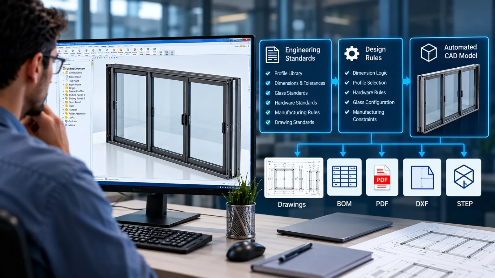
Engineering automation is most effective when it does more than repeat mouse clicks. The real value of rule-based CAD automation comes from converting established engineering knowledge into structured logic that CAD systems can execute consistently.
Manufacturing companies often have internal standards for dimensions, materials, component selection, configurations, clearances, naming conventions, drawing requirements and manufacturing constraints. Engineers apply these rules every day, often through experience and manual decision-making.
Manufacturers evaluating ways to standardize repetitive engineering tasks can explore our CAD automation services for customized solutions tailored to their existing design workflows.
As product variations increase, however, repeatedly applying the same rules can become a bottleneck.
Rule-based CAD automation provides a way to move these repeatable engineering decisions into a controlled digital workflow while keeping engineers responsible for design validation and non-standard decisions.
What Is Rule-Based CAD Automation?
Rule-based CAD automation is an approach to CAD automation where predefined engineering rules control how models, assemblies, drawings or engineering data are created or modified.
Instead of simply automating a sequence of commands, the system evaluates inputs and applies predefined logic.
For example:
Input:
Product width = 1200 mm
Material = Stainless Steel
Configuration = Double Door
Engineering rules:
- Select the appropriate frame configuration.
- Apply the corresponding material properties.
- Select compatible hardware.
- Update dependent dimensions.
- Generate the appropriate BOM structure.
- Apply the correct drawing template.
Output:
A consistent CAD configuration and corresponding engineering documentation.
The important distinction is that the automation is based on engineering logic, not just a recorded sequence of CAD operations.
Why Engineering Rules Are Difficult to Manage Manually
Engineering teams frequently develop internal standards over years of design and manufacturing experience.
These standards may determine:
- Minimum and maximum dimensions
- Material selection
- Component compatibility
- Standard hardware
- Thickness selection
- Hole patterns
- Clearances
- Structural requirements
- Manufacturing limitations
- Drawing standards
- Naming conventions
- BOM structures
- Configuration dependencies
In a small project, engineers can apply these rules manually.
The problem appears when the same product family has hundreds of configurations or when multiple engineers work on similar designs.
Different engineers may interpret the same rule differently. A standard component may be selected incorrectly, a dependent dimension may be missed, or a drawing may not reflect the latest configuration.
The challenge is therefore not simply CAD productivity.
It is consistency of engineering decisions.
From Engineering Knowledge to Automation Logic
A successful rule-based CAD automation project usually begins by converting engineering knowledge into explicit logic.
Consider a configurable sheet metal enclosure.
An engineer may know that:
- A larger enclosure requires additional reinforcement.
- Certain door sizes require specific hinge arrangements.
- A particular material requires a corresponding hardware set.
- Certain dimensions cannot exceed manufacturing limits.
- Specific configurations require additional supports.
An experienced engineer may apply these rules almost automatically.
For automation, however, these decisions need to be clearly defined.
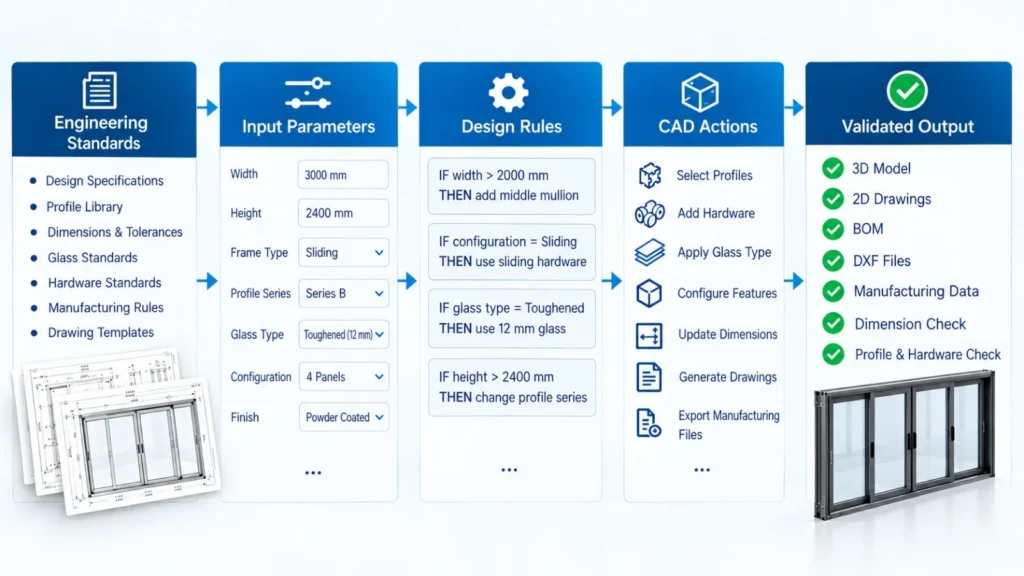
The process can be represented as:
Engineering Standard → Rule Definition → Input Parameters → Logic → CAD Action → Validation
This creates a structured connection between engineering knowledge and CAD execution. This approach is part of engineering design automation, where established design knowledge is translated into repeatable digital processes.
Step 1: Identify the Engineering Variables
The first step is determining which parameters influence the design.
Depending on the product, these could include:
- Length
- Width
- Height
- Thickness
- Material
- Load
- Capacity
- Number of components
- Product configuration
- Manufacturing process
- Customer-specific options
Not every CAD parameter needs to be automated.
The objective is to identify the variables that actually control the engineering outcome.
For example, changing the overall width of a cabinet might affect:
- Door dimensions
- Shelf spacing
- Frame members
- Hardware quantity
- BOM structure
- Drawing dimensions
These relationships become candidates for automation.
Step 2: Define Engineering Rules
Once the important variables are identified, the engineering rules can be documented.
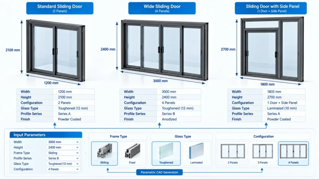
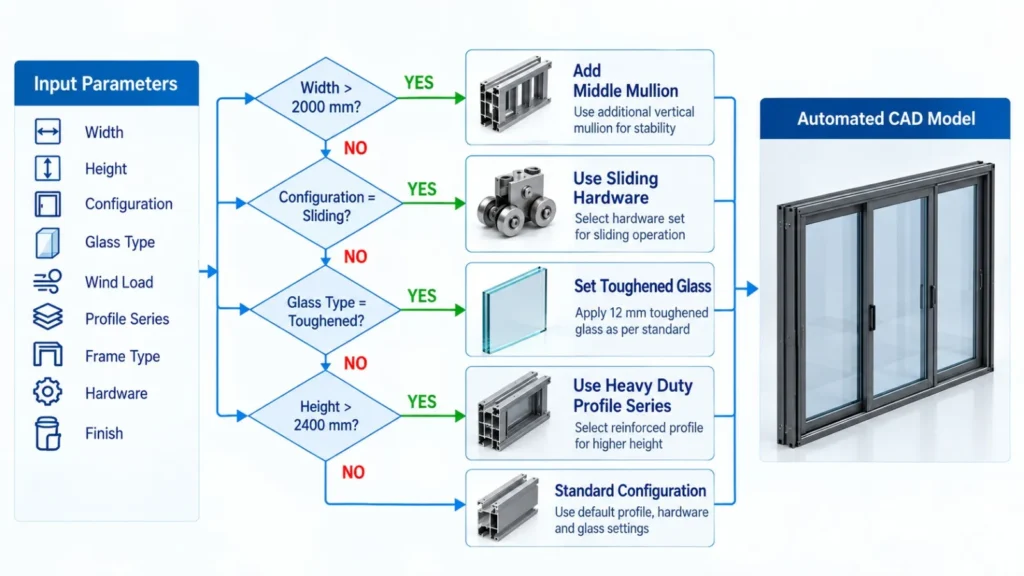
A simple rule may look like:
IF enclosure width exceeds a defined value
THEN add an additional support.
Another rule could be:
IF material = stainless steel
THEN select the corresponding hardware and material specification.
More complex systems can contain multiple conditions:
IF width exceeds a threshold
AND height exceeds a threshold
THEN use reinforcement configuration B.
This converts informal engineering knowledge into explicit logic.
The benefit is that the rule can then be reviewed, tested and maintained independently of the individual engineer who originally developed the design standard.
Step 3: Connect Rules to the CAD Model
The next stage is connecting the engineering logic to CAD parameters, features, configurations and components.
Depending on the CAD platform and workflow, this may involve:
- Parametric features
- Configurations
- Design tables
- API programming
- VBA
- .NET applications
- CAD add-ins
- iLogic
- Custom engineering tools
For example, SolidWorks API automation can connect predefined engineering rules with model parameters, configurations, assemblies and manufacturing documentation.
The CAD model then responds to the rule rather than requiring the engineer to manually modify every dependent feature.
This is where parametric CAD automation becomes particularly valuable.
Step 4: Automate Dependent Engineering Outputs
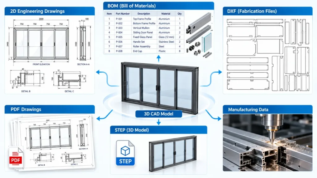
A CAD model is rarely the final deliverable.
Manufacturing may also require:
- 2D drawings
- BOMs
- PDFs
- DXF files
- STEP files
- Part lists
- Manufacturing data
- Custom properties
- Revision information
For sheet metal workflows, related processes such as automating DXF export and CNC data generation can help connect CAD design with downstream fabrication requirements.
A rule-based automation system can extend beyond geometry.
For example:
Customer/Product Input
↓
Engineering Rules
↓
CAD Configuration
↓
Assembly / Part Generation
↓
BOM
↓
Manufacturing Drawings
↓
Production Files
This creates a more connected engineering workflow.
The objective is not simply to make the CAD model faster.
It is to make the engineering process more repeatable from input to output.
Step 5: Build Validation Into the Workflow
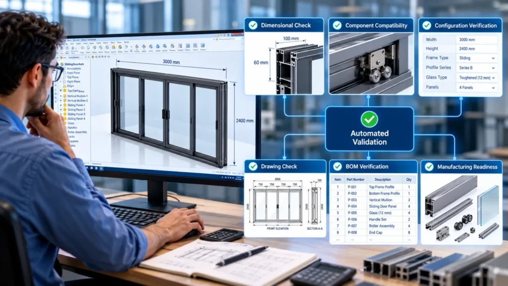
Automation should not eliminate engineering validation.
Instead, validation should become part of the automation architecture.
A well-designed system can check whether:
- Required parameters are entered.
- Dimensions fall within permitted ranges.
- Compatible components have been selected.
- Required properties are populated.
- Files have the correct names.
- Required configurations exist.
- BOM data is complete.
- Engineering outputs have been generated.
This creates a useful distinction between automation and autonomous engineering.
Automation performs predefined operations.
Engineering validation confirms that the resulting design satisfies the required technical criteria.
Human engineers should remain involved where engineering judgment, exceptions or new design decisions are required.
Rule-Based CAD Automation vs Simple Macros
Not every automation solution needs sophisticated rule logic.
A simple macro can be extremely useful for repetitive tasks such as:
- Exporting PDFs
- Updating properties
- Renaming files
- Extracting BOM information
- Performing batch operations
Rule-based automation becomes more valuable when the output depends on engineering conditions.
For configurable product families, product configurators can extend this concept by allowing users to select predefined options and generate corresponding product configurations.
For example:
Simple automation:
Click → Export PDF.
Rule-based automation:
Read configuration → determine drawing template → update properties → generate drawing → validate output → export PDF.
The second workflow requires an understanding of the engineering logic behind the process. This distinction is important when deciding how far CAD automation should be developed.
Where Rule-Based CAD Automation Works Well
Rule-based CAD automation is particularly suitable for products that have a stable design architecture with controlled variations.
Examples include:
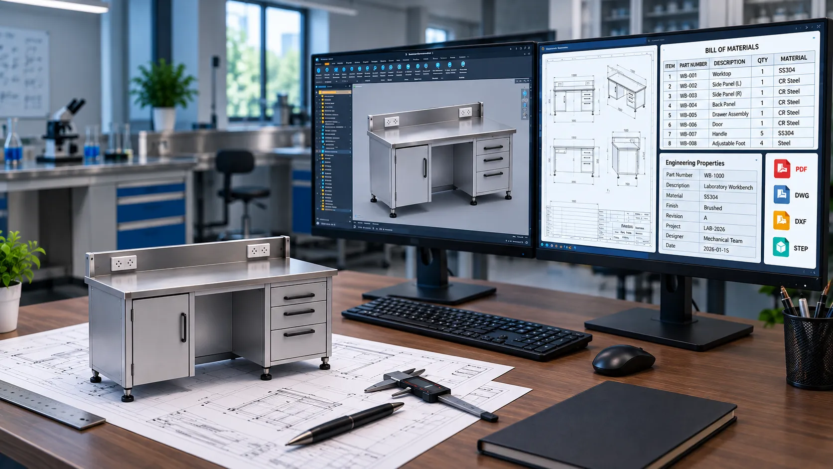
- Sheet Metal Products: Cabinets, enclosures, workbenches and fabricated components often contain repeatable dimensional and component relationships.
- Laboratory Furniture: Laboratory furniture can involve standardized modules, dimensions, materials, hardware and accessories while still requiring multiple configurations.
- Industrial Equipment: Machines and equipment may contain standard frames, mounting arrangements, components and configurable dimensions.
- Modular Products: Products based on predefined modules are strong candidates because the possible combinations can be translated into structured rules.
- Manufacturing Documentation: Drawing templates, BOM structures, file naming and output requirements can also be governed by predefined rules.
The common characteristic is not a specific industry. It is repeatability.
When Rule-Based CAD Automation Should Not Be Used
Automation is not automatically the right solution for every engineering task.
It may be unsuitable when:
- Every project is completely unique.
- Engineering decisions change significantly from project to project.
- There is insufficient design standardization.
- Product rules are not clearly understood.
- The automation would be more complicated than the manual task.
- Engineering validation cannot be defined reliably.
For highly customized engineering, automation may be better applied to documentation, data extraction or repetitive administrative tasks rather than core design decisions.
The goal should always be to automate where the engineering logic is sufficiently stable to justify it.
How to Make CAD Automation Maintainable
One of the biggest challenges in automation is maintaining the system when products and engineering standards change.
A good automation architecture should therefore separate:
Engineering Rules from Automation Code from CAD Models
This makes it easier to update a design rule without rebuilding the entire automation system.
For example, if a company’s standard hardware changes, the relevant rule or configuration data should be updated without requiring the complete automation workflow to be rewritten.
Documentation is equally important.
Each major rule should have a clear definition of:
- What triggers it
- What condition it evaluates
- What action it performs
- Which CAD elements it affects
- What exceptions exist
- How the result is validated
This helps engineering teams maintain the automation as products evolve.
Measuring the Value of Rule-Based CAD Automation
The effectiveness of CAD automation should not be measured only by how quickly a macro runs.
A broader evaluation should consider:
- Engineering Time: How much repetitive engineering effort is removed?
- Consistency: Are similar configurations produced using the same engineering standards?
- Error Reduction: Are common manual mistakes prevented or detected earlier?
- Scalability: Can the engineering team handle more product variations without proportionally increasing manual effort?
- Documentation Quality: Are drawings, BOMs and manufacturing files generated consistently?
- Maintainability: Can engineering rules be updated without rebuilding the complete system?
These measurements provide a more realistic view of the business value of engineering automation.
CAD Automation Is About Capturing Engineering Intent
The most useful CAD automation does not simply make engineers click faster.
It captures engineering intent.
When a company knows:
- which dimensions are allowed,
- which components are compatible,
- which configurations are valid,
- which manufacturing rules apply,
- which documentation is required,
that knowledge can potentially be structured into automation logic.
The CAD system then becomes part of a broader engineering workflow where predefined rules guide repeatable design operations.
This approach can help manufacturers move from isolated CAD automation toward more structured engineering process automation.
How Immersiv Techsphere Approaches CAD Automation
At Immersiv Techsphere, CAD automation is approached as an engineering workflow rather than simply a scripting exercise.
Our solutions can combine SolidWorks API, Autodesk Inventor automation, VBA, .NET development, parametric design and workflow integration depending on the requirements of the project.
Automation can be developed around existing engineering standards, CAD models, drawing templates, product structures and manufacturing requirements.
Typical objectives include:
- Converting repetitive engineering logic into automated workflows
- Standardizing configurable CAD models
- Automating dependent design operations
- Connecting CAD models with engineering data
- Generating consistent documentation
- Integrating CAD with PDM or downstream workflows
- Reducing repetitive manual intervention
The objective is straightforward:
Convert repeatable engineering knowledge into a controlled digital workflow.
Frequently Asked Questions
Rule-based CAD automation uses predefined engineering conditions and logic to control CAD design operations, configurations, components and engineering outputs.
basic macro generally automates a sequence of actions. Rule-based CAD automation can evaluate engineering conditions and determine which actions should be performed based on the input.
Yes. SolidWorks API, VBA, configurations and other development approaches can be used to build customized automation around existing SolidWorks workflows.
Yes. Autodesk Inventor provides automation capabilities that can be used to implement parameter-driven and rule-based design workflows.
No. CAD automation is intended to automate repeatable operations and predefined engineering logic. Engineers remain responsible for engineering judgment, validation and non-standard design decisions.
Products with repeatable structures and controlled variations are generally strong candidates, including sheet metal products, laboratory furniture, industrial equipment, modular products and configurable assemblies.
A workflow is a strong candidate when it contains repeatable inputs, clearly defined engineering rules, predictable outputs and sufficient design volume to justify automation.
Conclusion
Rule-based CAD automation provides a practical way to convert established engineering standards into repeatable digital design logic.
Instead of automating isolated CAD commands, manufacturers can structure relationships between inputs, engineering rules, CAD configurations and downstream documentation.
The result is a more consistent and scalable engineering workflow where automation handles predictable operations while engineers focus on validation, problem-solving and new design decisions.
For manufacturers managing configurable products or repetitive engineering workflows, the next step in CAD automation is not simply doing the same task faster.
It is making the engineering logic behind that task repeatable.
Have a Project in Mind?
Need help with 3D animation, industrial visualization, HSE training animation, or product visualization? Tell us about your project and our team will get back to you.